


XL EVAPORATIVE COOLING PRODUCTS
INSTALLATION
S140-600 IOM (NOV 07)
Page 6
The second step of installation is to mount the fan section to
the pan/coil section as follows:
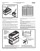
1.
Remove guards from both ends and remove the vertical
guard between the blowers to provide access to mounting
holes. Also, remove the motor housing access panel.
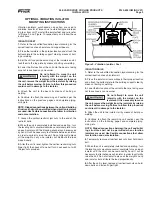
2.
Take mastic from parts box and place on coil section unit
body as shown in Figure 4a.
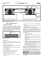
3.
Lower fan section to pan/coil section unit body so that the
blower support on the fan section rests on the fl anged edge
of the top fan mounting panel on the pan/coil section unit
body. Move the fan section to the pan/coil section unit body
until all mounting fl anges are touching. (Figure 4b)
4.
On each blower, install bolts with a fl at washer under both
the bolt and nut.
5.
Tighten all bolts connecting fan and pan/coil Sections
together before removing rigging.
6.
Align the V-belt drive and check tension in the belts using
the procedures in the section labeled "Fan Drives and Belts"
in this manual.
7.
Replace all guards and the motor hood access panel.
NOTE: When provided, mount desuperheater on top of
unit using holes provided in the mounting bracket. Note
that some units are shipped with the desuperheater
factory mounted. Assemble gas piping between desu-
perheater and condensing coils after fi nal positioning
of the desuperheater. Inter-gas piping is to be furnished
by others.
Figure 4b - Blower Assembly Mounting Instructions
Figure 4a - Mastic Placement For Blower Mounting
Figure 5 - XLC Unit Assembly With Desuperheater


