Johnson Controls Frick XL Скачать руководство пользователя страница 4

XL EVAPORATIVE COOLING PRODUCTS

INSTALLATION

S140-600 IOM (NOV 07)
Page 4

INSTALLATION TOOLS

To complete the installation of the XL Evaporative Condens-
ers, the following tools are needed:
 • 

Drift 

pins


•  8-foot straight edge

 • 

Level


•  Assorted open-end wrenches

 • 

Socket 

set


•  Belt tension gage

 • 

Tape 

measure

GENERAL INFORMATION

All XLC and XLP models should be anchored directly to 
concrete pads or concrete piers. These units may also be 
supported on structural “I” beams as outlined below.

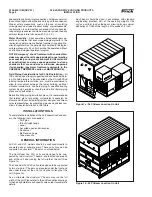
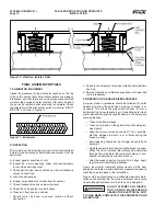
The Centrifugal Fan XLC units are designed to be sup-
ported by two structural “I” beams, one located under each 
end of the unit and running the full width of the unit (See 
Figure 1a).

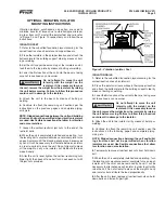
The Vane Axial Fan XLP units are designed to be supported 
by two structural “I” beams, one located under the front and 
one under the rear of the unit, running the full length of the 
unit (Figure 1b).

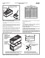
As an alternate, the structural “I” beams may run the full 
width of the unit. Please refer to the unit foundation drawings 
furnished by 

Frick 

for each specifi c sales order for complete 

details.

Figure 1b - XLP I-Beam Location On Unit

Figure 1a - XLC I-Beam Location On Unit

adequate/loose fi eld wiring/connections. All personnel must 
lock out and tag machinery before working on the condenser. 
Proper safety precautions such as the use of insulating 
soles/gloves and a trained “lookout buddy” are indispensable. 
Ice formation in cold weather can present fall/slip hazards. 
Icing safety procedures should be mandatory when the daily 
ambient temperature falls below 40°F (4.4°C).

Water Chemistry

 – All evaporative-cooled condensers op-

erate on principles that encourage biological growth in the 
recirculating water unless effective treatment is applied. Re-
circulating water must be periodically analyzed for biological 
culture plate counts. XL units should not be operated without 
an effective biological treatment program.

NOTE: Emergency “shock” treatment with chemical bio-
cides may upset the unit’s appropriate pH range (creating 
an excessively corrosive environment for the materials 
of construction) and may expose operators to strong 
chemicals that are corrosive or otherwise dangerous 
if mishandled (see water treatment comments in the 
CHEMICAL TREATMENT section of MAINTENANCE).

Field Piping Considerations for XL Unit Installation

 – All 

IDC units require strongly supported and anchored fi eld pip-
ing. No fi eld piping is to be supported by the XL itself. Wind 
loading, temperature variation, etc., must be considered to 
allow for movement between the tower, building, optional 
vibration isolator/rails, and fi eld piping. A qualifi ed cooling 
system design engineer should provide fi nal fi eld-piping 
plans and specifi cations.

Before fi nalizing piping installation plans, it is recommended 
that related plans for cooling system/plant expansion be 
discussed with your fi eld piping/system designer and Imeco 
sales representative. Incorporating pipe openings/sizes now 
allows for easier installation in the future.

Each beam should be sized in accordance with standard 
engineering practices, 55% of the operating weight of the 
unit as a uniform load on the beam, allowing for a maximum 
defl ection of 1/360 of the length, not to exceed 1/2 inch.

Содержание Frick XL

Страница 1: ...XL EVAPORATIVE COOLING PRODUCTS Form S140 600 IOM NOV 2007 INSTALLATION OPERATION MAINTENANCE File SERVICE MANUAL Section 140 Replaces S140 600 NOV 2005 Dist 3 3a 3b 3c ...

Страница 2: ...LC Spray Header Nozzle Orientation 13 Figure 13 XLP Spray Header Nozzle Orientation 13 Figure 14 Sheave Alignment 14 TABLES Table 1 XLC Foundation Layout Dimensions 5 Table 2 XLP Foundation Layout Dimensions 7 Table 3 Rigging Cable Lengths 8 NOTE Installation operation maintenance and repair of this equipment should only be accomplished by qualified person nel Failure to follow this note may resul...

Страница 3: ...ack aged and usually placed inside the pan section Mastic Bolts Nuts Washers and any accessory items TRANSIT DAMAGE CLAIMS All claims must be made by the consignee This is an ICC requirement Request immediate inspection by the agent of the carrier and be sure the proper forms are executed Contact Parts and Warranty Department to report damage or shortage claims UNIT IDENTIFICATION NOTE When inquir...

Страница 4: ...temperature falls below 40 F 4 4 C Water Chemistry All evaporative cooled condensers op erate on principles that encourage biological growth in the recirculating water unless effective treatment is applied Re circulating water must be periodically analyzed for biological culture plate counts XL units should not be operated without an effective biological treatment program NOTE Emergency shock trea...

Страница 5: ...epresents the center lines of the mounting holes in the unit The dashed lines show the location of the structural beams to which the unit is mounted XLC CENTRIFUGAL FAN UNITS XLC units are shipped in two pieces the pan coil section and the fan section The first step of the installation is to mount the pan coil section on the structural beams and bolt it to the beams The rigging of the two pieces i...

Страница 6: ...l mounting flanges are touching Figure 4b 4 On each blower install bolts with a flat washer under both the bolt and nut 5 Tighten all bolts connecting fan and pan coil Sections together before removing rigging 6 Align the V belt drive and check tension in the belts using the procedures in the section labeled Fan Drives and Belts in this manual 7 Replace all guards and the motor hood access panel N...

Страница 7: ...eams with bolts The rigging of the two pieces is shown in Figures 7a through 7c For cable lengths see Table 3 Figure 7a XLP Fan Section Rigging All models except 1570 2 and 1660 2 through 1880 2 Figure 7b XLP Fan Section Rigging Models 1570 2 and 1660 2 through 1880 2 MODEL A B C D E F S90 thru S175 S185 S190 S200 S205 145 141 57 5 1 625 0 75 S180 S195 S210 thru S270 145 141 68 5 M155 thru M280 12...

Страница 8: ... 7c Use drift pins in bolt holes to ensure proper alignment See Figure 8 NOTES 1 Use spreaders and blocking to protect casing from possible damage caused by slings 2 Remove eliminator tie straps and eliminators as nec essary to access lifters 3 Mount coil connection toward access door unless specified differently on product drawing 4 When provided mount desuperheater on top of unit using the holes...

Страница 9: ...annel can be removed by hand It will be necessary to alternate between isolators in order to uniformly raise the unit Do not attempt to place all the weight on any one isolator but distribute the load proportionally 9 After the unit is level tighten the vertical restraining nuts finger tight then back off one half turn Lock each nut with the jam nuts provided Figure 9 Vibration Isolator Feet ISOLA...

Страница 10: ...ance Manual for new belt run in procedures 3 BREAKING IN THE GALVANIZED SURFACES A proper break in procedure should be followed for water treatment to allow the galvanized surfaces to break in or passivate This allows the galvanized surfaces to form a self protecting zinc carbonate layer A qualified water treat ment specialist can provide specific details but following are some guidelines Clean al...

Страница 11: ...ntrol and freeze protection A common application for Vane Axial units is to cycle the operating fans to achieve capacity control Typically the fans are cycled off as capacity drops and finally the pump is shut off In cold weather operation Frick recommends that the pump should be the first item shut off to achieve capacity control By running the unit dry in cold applications the unit s drive is pr...

Страница 12: ...mended that the chemical feed for acid treatment be done in a tank such as a remote sump tank that allows complete diffusion of the chemical before it is pumped to the unit In addition to the chemical feed controls regular inspections of feed valve and chemical levels should be included in the preventative maintenance plan to avoid chemical concentration of the water outside of the accept able ran...

Страница 13: ...The coil should be examined monthly for signs of scale buildup and any obstructions between the tubes should be removed If there is evidence of scale buildup on the coil check the bleed valve for adequate bleed off If the bleed off valve is functioning properly contact your local water treat ment company for recommendations FAN MOTOR AND SPRAY PUMP MOTOR The motors should be checked and or lubrica...

Страница 14: ...ning Proper tension of a belt is very important to ensure maximum belt life If too little tension is applied the belt will slip Too much tension can reduce belt and bearing life It is not recom mended that belt dressing is used when belt slippage occurs as this will damage the belt and cause premature failure 1 Decrease the center distance between the sheaves so that the sheaves are somewhat loose...

Страница 15: ...e float is approximately 1 0 to 1 5 below the centerline of the overflow 11 Start spray pump and check for the proper rotation as indicated by sticker on pump motor On Remote installations where the unit pump was not furnished by the factory a globe valve should be installed in the pump discharge line and the pump flow rate adjusted to the correct water flow 12 Inspect spray nozzles and heat trans...

Страница 16: ...ews X X X Lubricate the fan and pump motors X Check fan for rotation without obstruction X X Check fan and pump motor for proper rotation X Drain sump and piping X Inspect protective finish X X Lubricate capacity control and or discharge X X X closure damper bearings and working joints Inspect adjust damper linkage X X X Inspect electric pan water level control X X X stilling chamber SAFETY Adequa...

Страница 17: ...____________________________ One Set FAN BUSHING ________________________________________________ One Set MOTOR BUSHING _____________________________________________ One Set FAN SHEAVE _________________________________________________ One Set MOTOR SHEAVE ______________________________________________ One Set FLOAT VALVE ASSEMBLY _______________________________________ One SPRAY NOZZLES __________...

Страница 18: ...XL EVAPORATIVE COOLING PRODUCTS NOTES S140 600 IOM NOV 07 Page 18 ...

Страница 19: ...XL EVAPORATIVE COOLING PRODUCTS NOTES S140 600 IOM NOV 07 Page 19 ...

Страница 20: ...DF1 and Modbus RTU I Q NET connects for local or remote access I Q NET can be applied to both new and existing systems I Q NET means precise control 24 hours a day seven days a week I Q NET distributed architecture mean faster easier economical installations I Q NET delivers increased operating efficiency and lowers energy costs Available on Frick screw compressors condensers evaporators AcuAir hy...

Отзывы: