570930-BUM-C-0112
2
Johnson Controls Unitary Products
SECTION II: TO OPERATE FURNACE
1. Be sure electrical power to furnace is turned on at the house-hold
service box.
2. Set wall thermostat to the desired temperature.
3. If furnace is equipped with Air Conditioning, the System Switch,
located at the wall thermostat, must be turned to HEAT in order for
the furnace to operate in the heating model.
The interlock system usually contains a heat-cool switch which must be
turned to either HEAT or COOL to activate either heating or cooling
operation.
If an interlock system has not been provided, the electrical supply to the
furnace must be turned OFF at the household service box, when the air
conditioner is being used. When operating the furnace, the electrical
supply to the air conditioner must be turned OFF.
TO SHUT FURNACE OFF
1. Turn thermostat to its lowest setting.
2. For complete shut-down, turn off electrical power at the household
service box.
SECTION III: SEQUENCE OF
OPERATION
When room thermostat calls for heat, 24-volt power is supplied to the
heating element switches. As soon as the first heating element switch
closes, the blower starts and power is supplied to the first heating ele-
ment. Each additional element is staged on in successive intervals.
When the room thermostat is satisfied and no more heat is required, the
elements sequence off in the reverse order and the blower will then turn
off.
LIMIT CONTROLS
Each element has an automatic limit switch which is wired into the cir-
cuit and shuts off power to that element if the heat at that point exceeds
the allowable maximum heat.
BLOWER REMOVAL
To remove blower from furnace, turn off power at household service
box, turn furnace circuit breakers OFF. Disconnect wiring to blower, and
remove five (5) screws holding blower in furnace and slide blower out
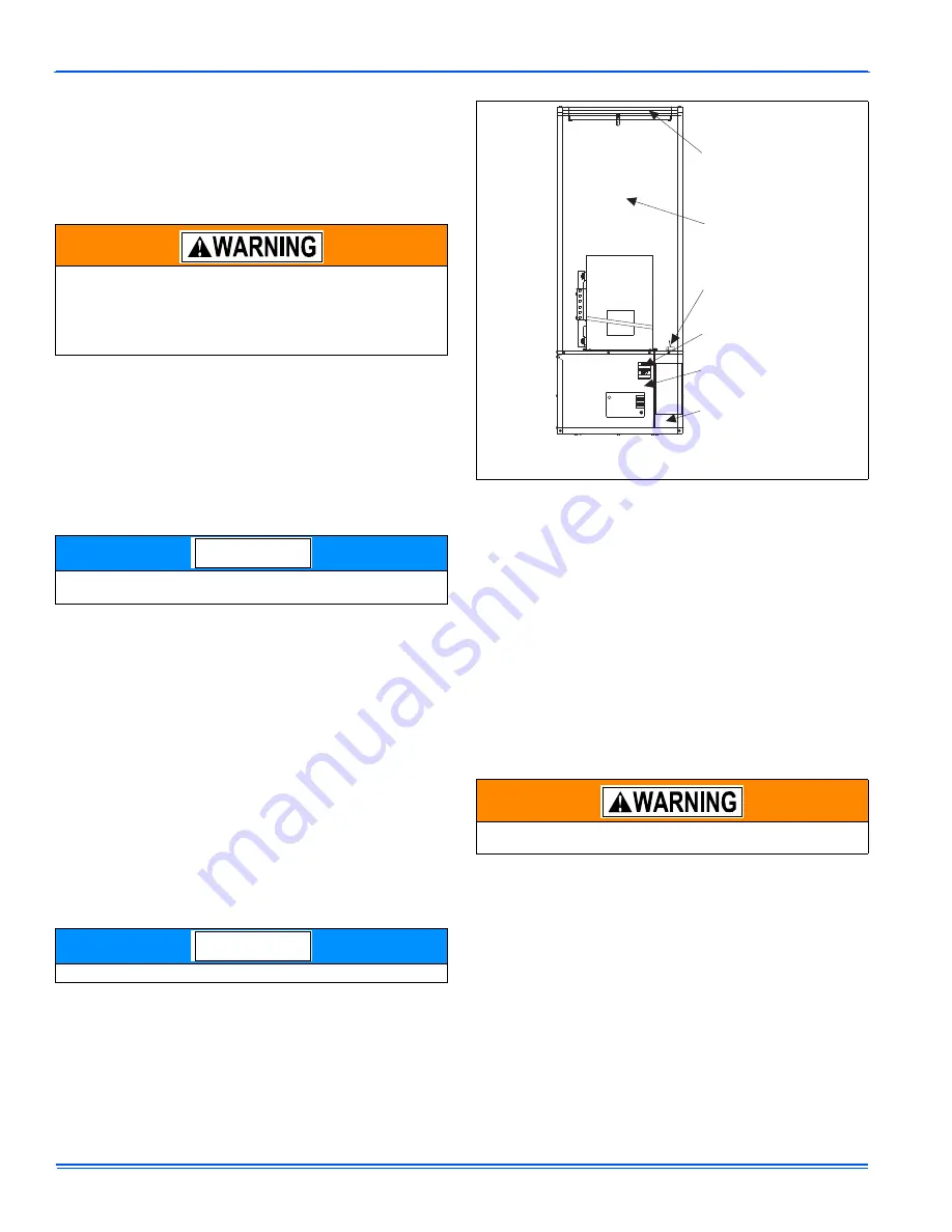
from front of the furnace. See Figure 1.
Re-install blower in reverse order when assembling back into furnace.
SECTION IV: FURNACE OPERATION
CIRCUIT BREAKERS
Your electric furnace is equipped with a unique safety feature - circuit
breakers. These circuit breakers are located behind the door of the fur-
nace, near the bottom of the furnace. See Figure 1. If a component
should fail inside the furnace, the circuit breakers will prevent damage
that can be caused by an electrical short. If the breakers ever trip, they
can be reset by first turning off the power to the furnace at the home's
circuit breaker panel. See Warning below. Then remove the furnace
door and reset the circuit breaker in the furnace. Re-install the furnace
door and turn the power back on at the home's breaker panel. If for
some reason these circuit breakers should trip again, a service techni-
cian should be contacted as a problem exists inside the furnace. A list
of authorized service centers is provided with every furnace and will
assist you in obtaining service for your furnace.
LUBRICATION
The blower motor bearings are factory sealed. Additional lubrication is
not required.
BLOWER ASSEMBLY
Every electric furnace comes equipped with a blower capable of operat-
ing a heat pump or air conditioner. With the addition of the proper heat
pump, you can enjoy comfort and savings all year long. An air condi-
tioner will also work with your furnace and will provide cool summer
days, at a very low operating cost.
If you have an air conditioner which does not use the furnace blower
for air distribution and operates completely independent of the fur-
nace, the thermostat system must have an interlock to prevent the
furnace and air conditioner from operating at the same time. Such
operation could cause equipment damage, energy waste and over-
heating of the home.
Furnace will still operate if room temperature falls below thermostat
setting.
Only authorized service technicians should remove the blower.
NOTICE
NOTICE
FIGURE 1:
Component Locations
You must first de-energize the furnace at the main household power
supply and lock it.
UL
R
FILTER (IN
DOWNFLOW
ONLY) *
CAVITY
FOR
COIL
THERMOSTAT
WIRES
CIRCUIT
BREAKERS
ELECTRIC
PANEL
FIELD WIRING
PROTECTIVE
SHIELD
Filter in the front panel when louvered doors
are used. Filter located in base for upflow units.
*


