527929-BIM-F-0911
26
Johnson Controls Unitary Products
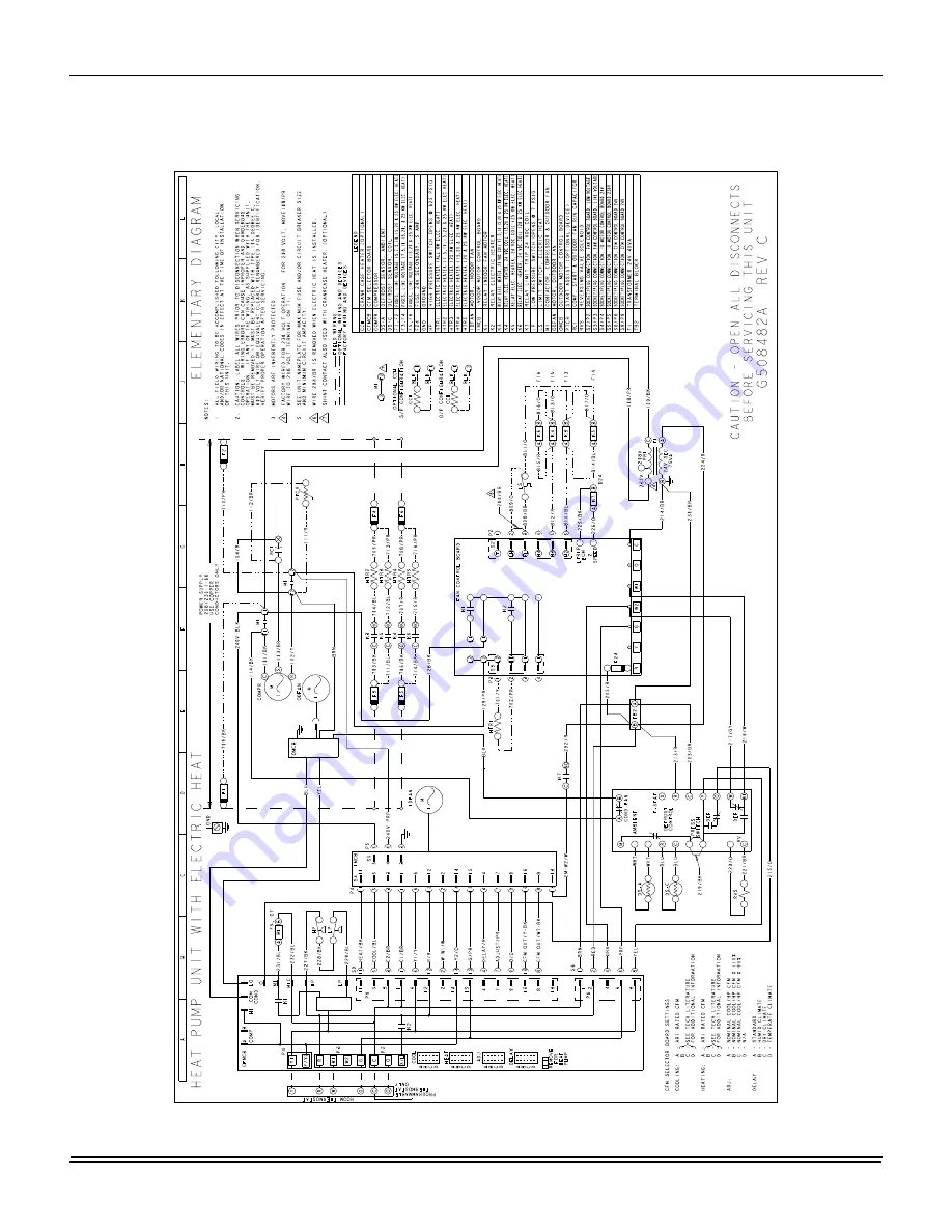
Wiring Diagrams
Typical BUQ024-060 Heat Pump 208/230-1-60 volt Wiring Diagram
Страница 1: ...y assembled heat pumps designed for outdoor installation on a roof top or a slab Field installed electric heater accessories are available to provide supplemental electric heat combined with electric...
Страница 2: ...to building electrical and mechanical codes Before performing service or maintenance operations on unit turn off main power switch to unit Electrical shock could cause personal injury Improper install...
Страница 3: ...ondenser Fan Motor Highly Efficient Enhanced Copper Tube Aluminum Fin Indoor Coil Highly Efficient Enhanced Copper Tube Aluminum Fin Outdoor Coil Decorative Protective Coil Guard ECM Direct Drive Blow...
Страница 4: ...the place of installation Rig the unit by attaching chain or cable slings to the lifting holes provided in the base rails Spreader bars whose length exceeds the largest dimension across the unit MUST...
Страница 5: ...SIDE RETURN AIR OPENING SIDE SUPPLY AIR OPENING LOW VOLTAGE CONN 7 8 DIA KNOCKOUT HIGH VOLTAGE CONN 1 31 32 DIA KNOCKOUT HIGH VOLTAGE CONN 7 8 DIA KNOCKOUT A 3 3 4 1 1 2 2 1 2 2 3 8 4 1 2 49 1 8 28 1...
Страница 6: ...T 26 3 4 CONDENSATE DRAIN 3 4 NPTF LOW VOLTAGE CONN 7 8 DIA KNOCKOUT HIGH VOLTAGE CONN 1 31 32 x 7 8 KNOCKOUT 22 1 2 43 1 2 40 1 2 4 14 1 2 28 3 8 14 1 2 BACK 3 3 8 SIDE RETURN AIR OPENING 14 1 2 4 1...
Страница 7: ...bottom supply and return air duct openings Roof Curb On applications when a roof curb is used the unit must be positioned on the curb so the front of the unit is tight against the curb Filters Single...
Страница 8: ...and or local ordinances The unit must be electrically grounded in accordance with local codes or in their absence with the N E C C E C Voltage tolerances which must be maintained at the compressor te...
Страница 9: ...or all field installed 24 volt wire Only required on units with supplemental electric heat PROGRAMMABLE THERMOSTAT ONLY THERMOSTAT CFM CONTROL BOARD TERMINAL STRIP 24 VOLT TRANSFORMER NOTE HEAT ANTICI...
Страница 10: ...NE04501006 7 5 10 2 36 1 41 7 45 1 52 1 50 60 2NE04501506 11 3 15 2 54 2 62 5 67 7 78 1 70 80 208 230 3 60 10 4 73 16 2 6 6 8 None 22 4 30 2NH04501025 7 5 10 1 20 8 24 1 48 5 52 5 50 60 2NH04501525 11...
Страница 11: ...4 47 4 54 5 ARI net capacity Mbh 23 28 6 35 2 42 46 5 54 0 EER 12 0 12 0 12 0 12 0 12 0 12 0 SEER 14 0 14 0 14 0 14 0 14 0 14 0 Nominal CFM 800 1050 1100 1400 1400 1500 System power KW 1 9 2 4 2 9 3...
Страница 12: ...p Prop Prop Prop Drive type Direct Direct Direct Direct Direct Direct Quantity of motors 1 1 1 1 1 1 Motor HP each 1 3 1 3 1 3 1 3 1 3 1 2 No speeds 1 1 1 1 1 1 RPM 1100 1100 1100 1100 1100 1100 Nomin...
Страница 13: ...880 121 140 160 181 Y1 W1 COOL C HEAT D 900 127 146 167 188 Y1 W1 COOL D HEAT A 800 99 118 137 157 Y1 W1 COOL D HEAT B 720 80 98 117 135 Y1 W1 COOL D HEAT C 880 121 140 160 181 Y1 W1 COOL D HEAT D 90...
Страница 14: ...High Y1 O COOL A 1400 350 398 445 491 535 579 624 670 714 Y1 O COOL B 1300 301 347 392 437 479 522 568 616 662 Y1 O COOL C 1500 399 449 498 546 591 636 680 725 767 Y1 O COOL D 1600 448 500 551 600 647...
Страница 15: ...48 060 5 0 Cool High Y1 O COOL A 1500 387 420 453 487 520 554 587 621 654 Y1 O COOL B 1600 486 520 553 587 620 654 687 721 754 Y1 O COOL C 1800 667 700 733 766 800 833 867 900 934 Y1 O COOL D 2000 857...
Страница 16: ...140 160 181 Y1 W1 COOL C HEAT D 900 127 146 167 188 Y1 W1 COOL D HEAT A 800 99 118 137 157 Y1 W1 COOL D HEAT B 720 80 98 117 135 Y1 W1 COOL D HEAT C 880 121 140 160 181 Y1 W1 COOL D HEAT D 900 127 146...
Страница 17: ...igh Y1 O COOL A 1400 350 398 445 491 535 579 624 670 714 Y1 O COOL B 1300 301 347 392 437 479 522 568 616 662 Y1 O COOL C 1500 399 449 498 546 591 636 680 725 767 Y1 O COOL D 1600 448 500 551 600 647...
Страница 18: ...8 060 5 0 Cool High Y1 O COOL A 1500 387 420 453 487 520 554 587 621 654 Y1 O COOL B 1600 486 520 553 587 620 654 687 721 754 Y1 O COOL C 1800 667 700 733 766 800 833 867 900 934 Y1 O COOL D 2000 857...
Страница 19: ...0 700 0 01 0 00 0 02 0 03 800 0 01 0 01 0 02 0 03 900 0 01 0 01 0 02 0 04 1000 0 02 0 01 0 02 0 04 1100 0 03 0 01 0 03 0 05 1200 0 04 0 02 0 03 0 06 1300 0 04 0 03 0 03 0 07 1400 0 04 0 04 0 03 0 08...
Страница 20: ...ashes once for every 100 CFM i e 12 flashes 1200 CFM Table 10 Electric Heat Minimum Supply Air Size Tons Voltage Minimum Supply Air CFM Heater kW 3 8 5 0 5 6 7 5 7 5 10 0 11 3 15 0 15 0 20 0 18 8 25 0...
Страница 21: ...supplied to the compressor and outdoor fan motor and the reversing valve switches to the cooling position When the fan switch on the thermostat is in the AUTO position the indoor blower motor is ener...
Страница 22: ...e unit is so equipped For trouble shooting purposes the defrost cycle can be manually initiated by shorting the TEST pins together for 5 seconds Defrost will terminate normally during the TEST mode De...
Страница 23: ...ON HEATER BANK 2 ELEC HEAT 10 SEC DELAY ON HEATER BANK 3 ELEC HEAT 20 SEC DELAY ON OFF HEATER BANK 3 ELEC HEAT INSTANT OFF HEATER BANK 2 ELEC HEAT 1 2 SEC DELAY OFF HEATER BANK 1 ELEC HEAT 1 SEC DELA...
Страница 24: ...ELAY DETERMINED BY DELAY JUMPER SETTING G W ON BLOWER INSTANT ON HEATER BANK 1 2 3 ELEC HEAT INSTANT ON HEATER BANK 4 5 6 ELEC HEAT 10 SEC DELAY ON OFF HEATER BANK 4 5 6 ELEC HEAT INSTANT OFF HEATER B...
Страница 25: ...suitable means If water is used to clean the coil be sure that the power to the unit is shut off prior to cleaning Troubleshooting Prior to any of the following maintenance procedures shut off all po...
Страница 26: ...527929 BIM F 0911 26 Johnson Controls Unitary Products Wiring Diagrams Typical BUQ024 060 Heat Pump 208 230 1 60 volt Wiring Diagram...
Страница 27: ...527929 BIM F 0911 Johnson Controls Unitary Products 27 Typical BUQ030 060 Heat Pump 230 3 60 volt Wiring Diagram...
Страница 28: ...527929 BIM F 0911 28 Johnson Controls Unitary Products Typical BUQ030 060 Heat Pump 460 3 60 volt Wiring Diagram...
Страница 29: ...arging cylinders and recovery equipment must be dedicated for use on R 410A systems only Manifold sets must be at least 700 psig high side and 180 psig low side with 550 psig retard All hoses must hav...