9
12
1
2
3
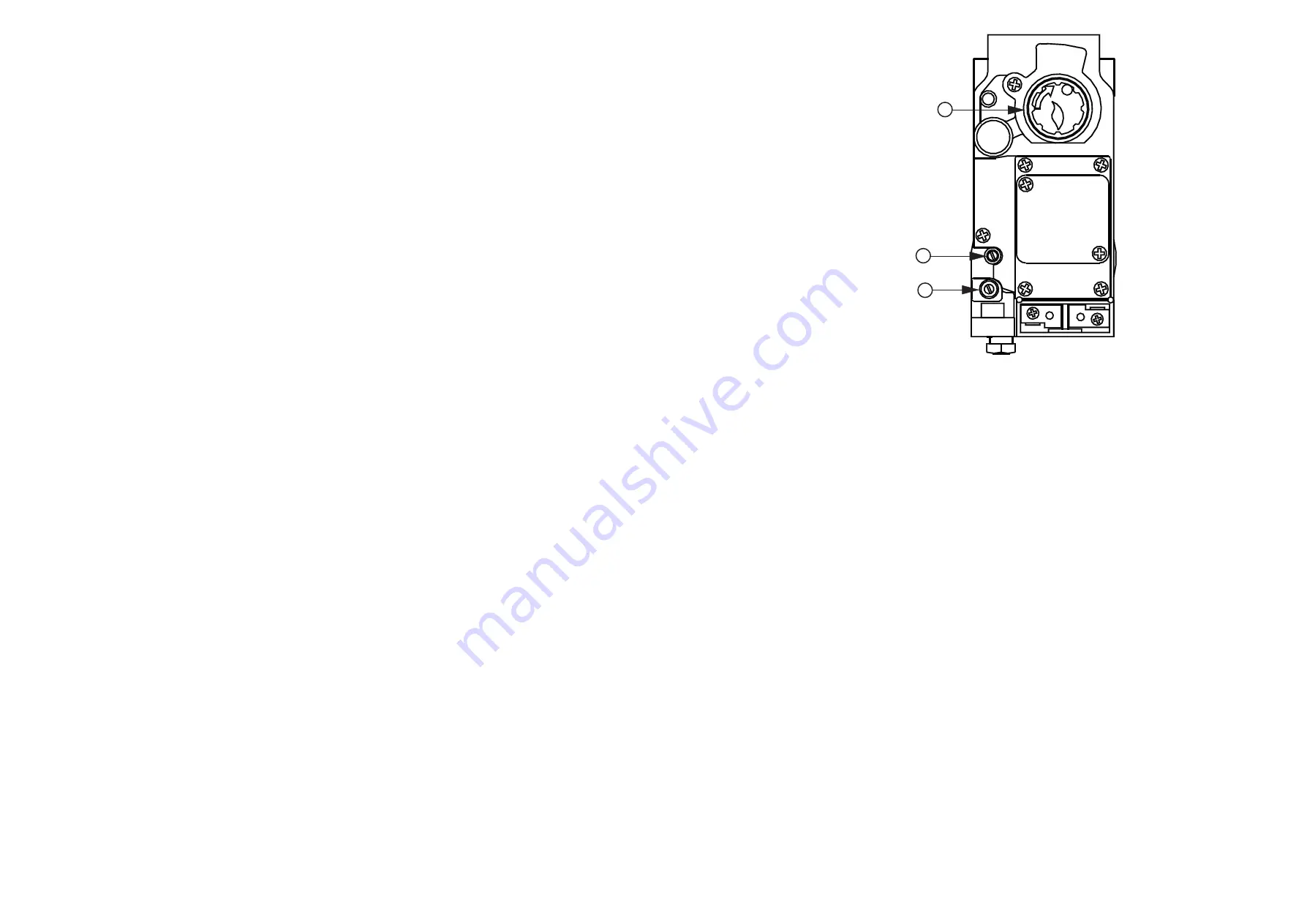
1.
Operating control
2.
Outlet pressure point
3.
Pilot adjuster
Fig. 5
Multifunctional Control
8.5
PILOT BURNER, THERMOCOUPLE AND ELECTRODE, REMOVAL AND REPLACEMENT:
8.5.1
Remove the Burner and Control Assembly as detailed in 8.2
8.5.2
Disconnect the Igniter lead from the Piezo unit.
8.5.3
Disconnect the Thermocouple from the Thermocouple adapter on the Multifunctional Control, taking care to avoid
damage to the Thermocouple Capillary.
8.5.4
Release the Pilot Feed Pipe from the Multifunctional Control.
8.5.5
Remove 2 x 4mm screws securing the Pilot Burner Assembly to the Burner and Control Assembly, and withdraw the
Pilot Burner Assembly.
8.5.6
Release the Thermocouple securing nut from the Pilot Burner assembly and withdraw the Thermocouple, taking care
to avoid damaging the Thermocouple Capillary.
8.5.7
Release the Electrode securing nut from the Pilot Burner Assembly and withdraw the Electrode.
8.5.8
Release the Pilot Feed Pipe securing nut from the Pilot Burner Assembly and withdraw the Pilot Feed Pipe and Pilot
Injector from the Pilot Burner Assembly, and disconnect the Pilot Injector from the Pilot Feed Pipe hook.
8.5.9
Refitting or replacement is in reverse order.
NOTE: When refitting or replacing the Thermocouple, tighten only to FINGER TIGHT + 1 FLAT.
8.6
MULTIFUNCTIONAL CONTROL REMOVAL:
8.6.1
Remove the Burner and Control Assembly as detailed in 8.2
8.6.2
Disconnect the Thermocouple at the Multifunctional Control (including the adapter), avoiding damage to the
capillary.
8.6.3
Disconnect the Pilot Feed Pipe from the Multifunctional Control.
8.6.4
Disconnect the Multifunctional Control input and output supply feeds.
8.6.5
Refitting or replacement is in reverse order.
8.7
PIEZO UNIT REMOVAL:
8.7.1
Disconnect 2 x conductors from Piezo unit.
8.7.2
Unscrew the Piezo retaining nut and remove the unit from its mounting bracket.
8.7.3
Refitting or replacement is in reverse order.
8.8
AIR CIRCULATING FAN, REMOVAL AND CLEANING:
8.8.1
Ensure that the electrical supply is isolated.
8.8.2
Remove the appliance lower and upper doors.
8.8.3
Disconnect the 230V connections (L/N/E) from the Fan Assembly.
8.8.4
Release 4 x screws securing the control panel, and withdraw the panel, avoiding damage to wiring.
8.8.5
Release 2 x Fan Assembly securing screws and withdraw the Fan Assembly from the Heater cabinet, avoiding
damage to fan blades.
8.8.6
Remove all dust from the impeller and motor, avoiding damage to the fan blades.
8.8.7
Refitting or replacement is in reverse order.
8.9
ELECTRICAL ASSEMBLY REMOVAL:
8.9.1
Ensure that the electrical supply is isolated.
8.9.2
Remove the appliance lower and upper doors.
8.9.3
Release 2 x 4mm screws securing the Limit Switch cover and the withdraw cover.
8.9.4
Release the Electrical Assembly cable clamp,
8.9.5
Disconnect the following:
a.
Disconnect 230V connections (L/N/E) from Fan Assembly,
b.
230V mains ‘
L
’, ‘
N
’ and ‘
E
’ from connection block terminals ‘
1
’ and ‘
3
’, and earth stud respectively,
c.
Room thermostat from connection block terminals ‘
5
’ and ‘
6
’,
d.
Limit Switch ‘
LOAD
’ and ‘
COMMON
’ connections,
e.
Fan Control ‘
LOAD
’, ‘
COMMON
’ and ‘
EARTH
’ connections,
6.7
AUTOMATIC CONTROLS CHECK
6.7.1
Set the TIME CONTROL to ‘
ON
’.
6.7.2
Turn the room thermostat slowly
clockwise until the Main Burner
ignites.
6.7.3
Ensure that the fan starts to
operate after a short period
(approx. 1-2 minutes).
6.7.4
When the temperature reaches
the control setting, ensure that
the Main Burner extinguishes
followed by the fan switching off
after a short period.
6.7.5
When the temperature falls below
the control setting, ensure that
the Main Burner re-ignites
followed by fan operation.
6.8
SAFETY CHECKS:
6.8.1
Check for gas soundness within
the appliance.
6.8.2
Spillage test:
Carry out a full
spillage test as follows, and
ensure that the flue operates
effectively with all doors closed
and any extractor fans in
operation.
NOTE:
If an extractor fan is situated in an adjoining or adjacent room, carry out the spillage test with the interconnecting doors open.
If the draught diverter is accessible:
a.
Introduce smoke into the draught diverter adjacent to an exit from the heat exchanger, by means a smoke match
or puffer.
b.
Ensure that there is no spillage present (indicated by displacement of smoke downwards and out of the draught
diverter.
If the Draught Diverter is not accessible:
a.
Introduce smoke, by means of
part
of a smoke pellet on a non-combustible support, into the heat exchanger.
b.
Extinguish the Main and Pilot Burners.
c.
Ensure that there is no spillage evident by visually observing the draught diverter location on the air heater.
d.
If spillage is evident, further investigation and rectification is required before re-testing the appliance.
WARNING: The appliance shall not be left connected to the gas supply unless it has successfully passed the above spillage test.
6.8.3
Turn OFF the gas supply at the service cock and ensure that the Multifunctional Control fail-safe operates within 60
secs (indicated by loud click from Multifunctional Control).
6.8.4
Turn the gas supply ON at the service cock.
6.8.5
Switch the electrical supply
OFF
.
6.8.6
Disconnect the fan at the electrical control panel.
6.8.7
Switch the electrical supply
ON
.
6.8.8
Ignite the Main and Pilot Burners as detailed in sub para 6.3.1 to 6.3.5
6.8.9
Ensure that the Limit Switch operates, indicated by the Main Burner extinguishing, (approximately 2 to 3 minutes).
6.8.10 Switch the electrical supply
OFF
.
6.8.11 Reconnect the Air Heater Fan.
6.8.12 Switch the electrical supply
ON
.
6.8.13 Ensure that the Main Burner re-ignites when the appliance temperature reduces, (note: with the fan disconnected, there
may be some delay before the Main Burner re-ignites).


