background image

22 of 31 


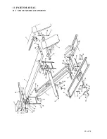
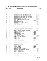
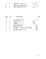
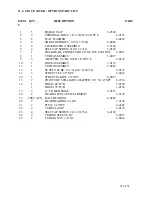
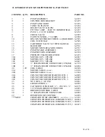
11.2  SPACE SAVER ALIGNMENT MAIN FRAME ASSEMBLY - PART LIST 
 
ITEM 


QTY.  DESCRIPTION 

     PART 

 
   1 

      2   

BASE FRAME WELDMENT 


4-0160 

   3 

      2   

SCISSOR WELDMENT 


4-0002 

   4 

      1   

ALIGNMENT DECK, LEFT SIDE (144”W/B) 


4-0114 


      1   

ALIGNMENT DECK, LEFT SIDE (172”W/B) 


4-0116 

   5 

      1   

ALIGNMENT DECK, RIGHT SIDE (144”W/B) 


4-0127 


      1   

ALIGNMENT DECK, RIGHT SIDE (172”W/B) 


4-0137 

   6 

      2   

APPROACH RAMP (144”W/B) 


3-0242  


      2   

RAMP ASSEMBLY 

W/ ROLLER


(172”W/B) 

  3-0905 

   7 

      4   

RAMP PIN 


1-1887 

   8 

      2   

FRONT WHEEL STOP 


2-0851 

   9 

     26   

HEX BOLT, ½” - 13UNC X 1 ½”LG. 


6-0291 

  10 

     44   

HEX NUT, ½” - 13UNC 


6-0035 

  11 

     24   

LOCK WASHER, ½”I.D. 


6-0059 

  12 

      4   

3/4”I.D. FLAT WASHER 


6-0978 

  13 

      2   

LEVELLING LEG, FRONT-LEFT, REAR-RIGHT  

3-0248 

  14 

      2   

LEVELLING LEG, FRONT-RIGHT, REAR-LEFT  

3-0272 

  15 

      4   

PLUNGER PIN ASSEMBLY 


2-0086 

  16 

      1   

SAFETY RELEASE CONNECTING ROD   


2-0071 

  17 

      4   

FULCRUM PIN, 1 ¼” DIA.   


1-0106 

  18 

      8   

BUSHING, 1”I.D. 


6-0085 

  19 

      8   

END HINGE PIN, 1” DIA.   


1-0107 

  20 

      4   

CAM FOLLOWER   


6-0637 

  21 

      4   

JAM NUT, 5/8” - 18UNF 


6-0040 

  22 

      2   

SAFETY BAR WELDMENT 


2-1683  

  23 

      2   

SAFETY PIN   


1-0547 

  24 

      2   

SAFETY PEDAL 


2-0194 

  25 

      2   

SAFETY RELEASE TAB 


1-2169 

  26 

      2   

SAFETY RELEASE ROD 


2-2133 

  27 

      6   

HEX BOLT, ¼” - 20UNC X 1 ¼”LG. 


6-0027 

  28 

     14   

LOCK WASHER, ¼”I.D. 


6-0056 

  29 

      6   

HEX NUT, ¼” - 20UNC 


6-0032 

  30 

      1   

CENTER COVER 


3-0951 

  31 

      4   

GREASE NIPPLE 


6-0000 

  32 

      4   

CAM FOLLOWER   


6-0077 

  33 

      2   

PULL OUT STEP ASSEMBLY 


2-0362 

  34 

      1   

REAR CROSSMEMBER WELDMENT 


3-0251  


  35 

      2   

SAFETY WALK TAPE 


1-0749 

  36 

     26   

PLAIN WASHER, ½”I.D. 


6-0063 

  37 

      4   

FLATWASHER, ¼”I.D. 


6-0060 

  38 

      1   

FRONT CROSSMEMBER (172” W/B) 


3-0007 

  39 

      2   

TOE GUARD  


1-0086 

  40 

     8 


HEX BOLT, ¼” - 20UNC X ¾”LG.   


6-0178  


Содержание Spacesaver 469000

Страница 1: ...INSTALLING OPERATING SERVICING OR MAINTAINING THE LIFT SAVE THIS MANUAL NOV 2007 REV B INSTALLATION and OPERATION MANUAL 6 1653 SPACESAVER 9000 SERIES SPACESAVER 9000 SERIES 309 EXCHANGE AVENUE CONWAY ARKANSAS 72032 TEL 501 450 1500 FAX 501 450 1585 ...

Страница 2: ... AND 9005 16 6 10 INSTALLATION FOR ALL MODELS 17 7 OPERATING INSTRUCTIONS 17 7 1 RAISING THE LIFT 17 7 2 LOWERING THE LIFT 18 8 FINAL CHECK OF ASSEMBLED LIFT 19 9 OPERATION TEST WITH VEHICLE 19 10 RECOMMENDED MAINTENANCE 20 11 PARTS MANUAL 21 11 1 SPACE SAVER ALIGNMENT 21 11 2 SPACE SAVER ALIGNMENT MAIN FRAME ASSEMBLY PART LIST 22 11 3 SPACE SAVER SERVICE RUST PROOFER 24 11 4 SPACE SAVER MAIN FRAM...

Страница 3: ...the safety devices 4 Only trained and authorized personnel should operate the lift Do not allow customers or bystanders to operate the lift or be in the lift area 5 Caution Never work under the lift unless the mechanical safety locks are engaged 6 Always keep the lift area free of obstruction and debris Grease and oil spills should always be cleaned up immediately 7 Never raise vehicle with passen...

Страница 4: ...es installation operator training and owner employer responsibilities please refer to Lifting It Right ALI SM and Safety Tips ALI ST For additional instruction on general requirements for lift operation please refer to Automotive Lift Safety Requirements For Operation Inspection and Maintenance ANSI ALI ALOIM ATTENTION This lift is intended for indoor installation only It is prohibited to install ...

Страница 5: ...5 of 31 2 SAFETY WARNING DECALS Be sure the operator is aware and underastands all safety warning lables and follows them accordingly ...

Страница 6: ... 221 5613mm Overall Length A 9005 172 W B 264 6706mm Overall Length A 9000 144 W B 213 5410mm Overall Length A 9006 172 W B 256 6502mm Max Raised Height 72 1829mm Min Lowered Height 8 3 4 222mm Lifting Time 60 Sec Power Requirements Standard 230 Volts 1Ph 60Hz Shipping Weight 144 W B 3450 lbs 1804 kg Shipping Weight 172 W B 4180 lbs 1900 kg Figure 1 Lift dimensions ...

Страница 7: ... Bar 1pc Front Tie Bar 9000 9005 9006 2pcs Ramp Pins 2pcs Safety Toe Guard 2pcs Safety Release Pedal 2pcs Mechanical Safety Release Rod 1pc Mechanical Safety Release Connecting Rod 2pcs Safety Release Tab 5pcs Hydraulic Line Covers 1pc Center Cover 1pc Center Hydraulic Line 3pc Recoil Hose 2pcs 3 8 Hydraulic Tubing 20 LG 2pcs Front Levelling Leg Bracket Inside 9004 9005 4pcs Levelling Leg Bracket ...

Страница 8: ...ommencing with the installation IMPORTANT It is the user s responsibility to provide a satisfactory installation area for the lift Lifts should only be installed on level concrete floors with a minimum thickness of five 5 inches or 130 mm Concrete must have a minimum strength of 4000 psi or 30 MPa and should be aged thirty 30 days prior to installation Please consult the architect contractor or en...

Страница 9: ...des Recommended overhead clearance is a minimum of twelve 12 foot ceiling providing 6 feet for the maximum lift height and 6 feet for the supported vehicle For vehicles taller than 6 feet it is recommended that the user provides additional overhead clearance or a shut off mechanism to stop the lift from raising the vehicle too high IMPORTANT DO NOT UNBOLT SHIPPING CLAMPS HOLDING EACH MAIN FRAME AS...

Страница 10: ...es 5 Draw a line parallel to the front of the lift 39 991mm back for 144 W B models and 52 1321mm back for 172 W B models Align the front of each base frame assembly onto this line 6 Check the floor in the outline for the highest point using a four 4 foot level Mark this location reference will be made to it later during the leveling procedure 6 2 UNPACKING PROCEDURE 1 Cut and remove the metal ban...

Страница 11: ... Tighten all the supply lines You may now anchor the hydraulic power pack floor or wall mount 6 Connect one end of the center hydraulic line to the outlet side of the left main frame assembly and the other end to the inlet side of the right main frame assembly Tighten the hydraulic line in place so that it runs along the floor giving it a low profile IMPORTANT THE SHIPPING CLAMPS HOLDING EACH MAIN...

Страница 12: ...UTTON TO LOWER THE LIFT REPEAT THIS PROCEDURE THREE 3 TIMES TO RELIEVE AIR FROM THE HYDRAULIC SYSTEM CHECK FOR HYDRAULIC LEAKS AT ALL CONNECTIONS 6 5 MECHANICAL SAFETY INSTALLATION 1 Locate the two 2 mechanical safety release rods and one 1 mechanical safety release connecting rod 2 Raise the lift by pressing the up button on the hand control 3 Turn off the power supply to the power pack 4 Slide e...

Страница 13: ...ts nuts and lock washers 8 Install pedal safety guards One on each baseframe using the 20UNC x long hex bolts nuts and lock washers 9 Install the safety release connecting rod between the safety release rods using 20 UNC x 1 long hex bolt nut and lock washers one on each end of the rod 10 Tighten all installation hardware 11 Place the mechanical safety locking bars back in their engaging positions...

Страница 14: ...a very important procedure and time must be taken to do it correctly 1 The highest point on the floor noted from Section 4 1 step 6 is the point from which the base frame will be levelled from A quick check using a four 4 foot level across the base frame should again verify that this is the highest point 2 Starting at the corner closest to the highest point check along the length of the base frame...

Страница 15: ... through the floor at each of the six 6 anchor bolt locations on each of the base frames Make sure that the 1 2 concrete drill bit is in good condition Refer to Figure 6 3 Assemble the nut and washer onto the 1 2 x 4 1 2 long wedge anchor bolts supplied A minimum of six threads must be visible below the surface of the nut 4 Clean out the drilling dust from the holes and hammer in the anchors until...

Страница 16: ... hardware and place in their respective locations NOTE On the long alignment models 9005 the rear levelling legs fold up toward the rear whereas on the shorter alignment model 9004 the legs fold up toward the front of the lift 3 Position but do not tighten all levelling leg brackets The levelling legs should hang in the brackets and swing freely Thrust washers are provided to take up any side play...

Страница 17: ... frame of the left main frame assembly 4 Using a rotary hammer drill and a concrete drill bit drill all line cover locations Using the concrete nails supplied fasten the line covers to the floor 5 Install the approach ramps using ramp pins washers and cotter pins 6 Tighten all bolts on crossmember s 7 OPERATING INSTRUCTIONS 7 1 RAISING THE LIFT 1 If the lift is equipped with Sliding Jack Beam s be...

Страница 18: ... WORK UNDER A VEHICLE OR THE LIFT UNLESS IT IS POSITIONED ON BOTH MECHANICAL SAFETIES 7 2 LOWERING THE LIFT 1 Check that there are no obstructions under the lift or vehicle Be sure that the Sliding Jack Beams are fully lowered and positioned at the front or mid section of the lift 2 Raise the lift by pressing the up button until the mechanical safety bars are off of their stops Stop raising 3 Depr...

Страница 19: ... b ANSI ALI Lift It Right Manual ____ c ANSI ALI Safety Tip Card ____ d ANSI ALI ALIS Safety Requirements for Installation ____ and Service of Automotive Lifts e ANSI ALI Quick Reference Guide ____ 8 Train end user on operation of lift ____ 9 OPERATION TEST WITH VEHICLE 1 Lower lift to ground 2 Drive vehicle on to lift 3 Raise lift to and lower onto 3 4 lock positions during full rise to ensure al...

Страница 20: ...e to sand and salt NOTE Locking pins should always be installed on front and rear plates before attempting to drive a vehicle on or off the lift 8 If uneven lifting occurs as described in section 5 1 3 the crossmember s will need to be re adjusted Quarterly Slip Plate Maintenance 1 Remove top Slip Plate covers by first removing the four 4 shoulder bolts on each cover 2 Remove polyethylene bearing ...

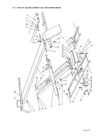
Страница 21: ...21 of 31 11 PARTS MANUAL 11 1 SPACE SAVER ALIGNMENT ...

Страница 22: ...2 LEVELLING LEG FRONT RIGHT REAR LEFT 3 0272 15 4 PLUNGER PIN ASSEMBLY 2 0086 16 1 SAFETY RELEASE CONNECTING ROD 2 0071 17 4 FULCRUM PIN 1 DIA 1 0106 18 8 BUSHING 1 I D 6 0085 19 8 END HINGE PIN 1 DIA 1 0107 20 4 CAM FOLLOWER 6 0637 21 4 JAM NUT 5 8 18UNF 6 0040 22 2 SAFETY BAR WELDMENT 2 1683 23 2 SAFETY PIN 1 0547 24 2 SAFETY PEDAL 2 0194 25 2 SAFETY RELEASE TAB 1 2169 26 2 SAFETY RELEASE ROD 2 ...

Страница 23: ...0140 ITEM QTY DESCRIPTION PART 47 2 FLAT SHIPPING BRACKET 2 0266 48 4 BUSHING 1 I D 6 0084 49 12 COTTER PIN 1 8 X 2 LG 6 0115 50 4 WASHER 1 0140 51 4 SPRING PIN 3 16 X 2 LG 6 0146 52 6 FLATWASHER SAE 6 0439 53 2 SHIPPING BRACKET 2 0112 54 6 HEX BOLT 13UNC X 1 LG 144 W B 6 0291 6 HEX BOLT 13UNC X 1 LG 172 W B 6 0047 55 4 FLAT HD 20UNC x LG 6 1086 56 4 COTTER PIN 1 8 X 1 LG 6 0738 ...

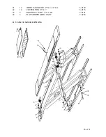
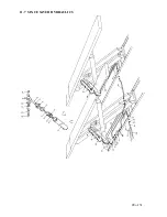
Страница 24: ...24 of 31 11 3 SPACE SAVER SERVICE RUST PROOFER ...

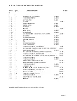
Страница 25: ... 0291 10 22 HEX NUT 1 2 13UNC 6 0035 11 14 LOCKWASHER 1 2 ID 6 0059 12 6 1 2 SAE FLAT WASHER 6 0439 13 4 SPRING PIN 3 16 X 2 LG 6 0146 14 4 WASHER 1 0140 15 4 BUSHING 1 1 4 ID 6 0084 16 1 SAFETY RELEASE CONNECTING ROD 2 0071 17 4 FULCRUM PIN 1 1 4 DIA 1 0096 18 8 BUSHING BRONZE 1 ID 6 0085 19 8 END HINGE 1 DIA 1 0107 20 4 CAM FOLLOWER 6 0637 21 4 JAM NUT 5 8 18UNF 6 0040 22 2 SAFETY BAR WELDMENT 2...

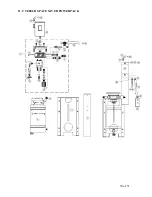
Страница 26: ...26 of 31 41 12 WEDGE ANCHOR 1 2 X 4 1 2 LG 6 0140 42 14 COTTER PIN 1 8 X 2 6 0115 43 4 CONCRETE NAIL 1 4 X 1 LG 6 0141 44 2 FLAT SHIPPING BRACKET 2 0266 11 5 SPACE SAVER OPTIONS ...

Страница 27: ...8 JIC M TO 1 4 NPT F 6 0118 10 1 HOSE ASSEMBLY 1 0119 11 1 TUBE ASSEMBLY 2 0062 12 1 SUPPLY TUBE 3 8 X 049 X 20 LG 6 0171 13 3 STREET TEE 1 4 NPT 6 0014 14 1 STREET ELBOW 1 4 NPT 6 0015 15 2 POLYTUBE STRAIGHT ADAPTER 3 8 X 1 4 NPT 6 0710 16 1 HOSE 144 W B 1 0120 1 HOSE 172 W B 1 0139 17 3 12 COILED HOSE 6 0337 18 2 REAR SLIP PLATE WELDMENT 3 0197 19 1 SET 225 BALL BEARING 6 0829 20 2 REAR BEARING ...

Страница 28: ...28 of 31 11 7 SPACE SAVER HYDRAULICS ...

Страница 29: ...E 6 0422 18 2 TUBE ASSEMBLY CYLINDER 1 0093 19 4 BULKHEAD CONNECTOR 3 8 JIC C W JAM NUT 6 0013 20 2 HOSE ASSEMBLY 2 2136 21 1 BULKHEAD ADAPTER 3 8 BSF TO 3 8 JIC 6 0176 22 1 TUBE ASSEMBLY RIGHT SIDE 2 0068 23 1 BULKHEAD 90 ELBOW 3 8 JIC M C W JAM NUT 6 0012 24 1 TUBE ASSEMBLY 2 0064 25 1 TUBE ASSEMBLY 2 0182 26 2 ADAPTOR 3 8 BSF TO 3 8 JIC 6 0156 27 1 FLOW DIVIDER WITH FITTINGS 6 0173 28 1 TUBE AS...

Страница 30: ...30 of 31 11 9 9 000 LB SPACE SAVER POWER PACK ...

Страница 31: ...REATHER 6 3223 18A 1 MOTOR 220V 1 PHASE 6 0087 18B 1 MOTOR 220V 3 PHASE 6 0446 18C 1 MOTOR 575V 3 PHASE 6 0447 19A 2 STRAIN RELIEF CONNECTOR 1 PHASE 6 1370 19B 2 STRAIN RELIEF CONNECTOR 3 PHASE 6 0094 20 3 FT COIL CABLE 8 0306 21A 1 MOTOR CABLE 1 PHASE 1 0104 21B 1 MOTOR CABLE 3 PHASE 1 1824 22A 1 CONTACTOR MOTOR STARTER 220V 1 6 0805 22B 1 CONTACTOR MOTOR STARTER 220V 3 6 0809 22C 1 CONTACTOR MOT...

Отзывы: