10 of 31
1. After selecting the location best suited for your lift, draw a line parallel to the front of the
lift, approximately 72” (1829mm) back from the cabinet/work bench area. This will be
the approximate location of the front of the lift. Refer to
Figure 2
.
NOTE:
Check the installation area for obstructions. (Overhead; light fixtures, heating ducts,
ceiling, and In-ground; floor drains, electrical, etc...)
2.
Mark on the floor an outline matching the dimensions listed.
SPACE SAVER
- Alignment Model 9004: 144"(3658mm) Wheel Base. 221"(5613mm) x
84"(2134mm).
9000 SERIES
- Alignment Model 9005: 172"(4369mm) Wheel Base. 264"(6706mm) x
84"(2134mm).
- Service Model 9000:
144"(3658mm) Wheel Base. 213"(5410mm) x
84"(2134mm).
- Service Model 9006:
172"(4369mm) Wheel Base. 256"(6502mm) x
84"(2134mm).
3.
Draw a center line down the middle of the outline starting at the front of the lift location
and ending at the rear approach ramps.
4.
Draw two lines parallel to the center line 18” (457mm) on either side to locate the inside
of the baseframes.
5. Draw a line parallel to the front of the lift, 39” (991mm) back for 144”W/B models and
52” (1321mm) back for 172”W/B models. Align the front of each base frame assembly onto
this
line.
6.
Check the floor in the outline for the highest point using a four (4) foot level. Mark this
location, reference will be made to it later during the leveling procedure.
6.2 UNPACKING
PROCEDURE
1. Cut and remove the metal banding straps that hold the accessory box (and sliding Jack
Beams if so equipped) and place in a convenient location near the installation area.
2. Cut and remove the metal banding straps surrounding the Two Main Frame Assemblies.
Position the Main Frame Assemblies in the location previously marked in the bay layout.
NOTE:
To distinguish between the left and right Main Frame Assemblies the pull-out step
should be located at the front facing outward from the lift. All measurements are to be
taken from the front of the lift.
3. Check that the inside of the base frames are 18" (457mm) away from the center line at
both the front and rear of each mainframe assembly and that the front of each base frame
is on the line drawn in step 5 of the bay layout, section 4.1.
6.3 HYDRAULIC
INSTALLATION
Содержание Spacesaver 469000
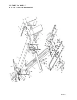
Страница 21: ...21 of 31 11 PARTS MANUAL 11 1 SPACE SAVER ALIGNMENT ...
Страница 24: ...24 of 31 11 3 SPACE SAVER SERVICE RUST PROOFER ...
Страница 28: ...28 of 31 11 7 SPACE SAVER HYDRAULICS ...
Страница 30: ...30 of 31 11 9 9 000 LB SPACE SAVER POWER PACK ...


