Anhui JNGE Power Co., LTD
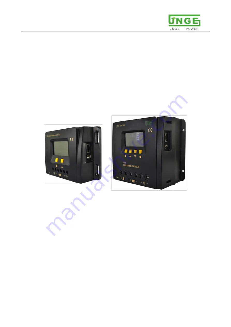
JN-K
、
JN-R Series PWM Solar Charge
Controller
Product manual
Anhui JNGE Power Co.,LTD
ADD
:
No.99 Yonghe Rd,High-Tech Zone,Hefei,Anhui
Phone
0551-65372576
Страница 1: ...Anhui JNGE Power Co LTD JN K JN R Series PWM Solar Charge Controller Product manual Anhui JNGE Power Co LTD ADD No 99 Yonghe Rd High Tech Zone Hefei Anhui Phone 0551 65372576 ...
Страница 2: ...stallation instructions 5 3 1 Installation precautions 5 3 2 Installation instructions 6 3 3 Wiring 7 3 4 Photovoltaic array requirements 8 3 5 Cable type selection requirements 8 4 Instructions for operation 9 4 1 LCD display 9 4 2 Key 10 4 3 Setting operation 11 5 Equipment parameters 12 5 1 Protection function 12 5 2 Troubleshooting 13 5 3 System maintenance 14 6 Warranty commitment 14 7 Equipm...
Страница 3: ...on tips 1 2 Safety instructions Warning All installation of the controller must be performed by a professional technician The professional technical personnel must go through the special training read the manual completely and master the operation related safety matters The company shall not be liable for any injury caused by non professional installation operation Failure to install and operate t...
Страница 4: ...l the controller in flammable or explosive places or storage places for flammable or explosive materials Do not install the controller where there is explosive danger Do not install the controller where lightning may strike Do not install the controller where there is a lot of salt spray When controller is running it is necessary to ensure the normal air convection around it The controller shall b...
Страница 5: ...tem performance Adopt imported power MOSFET as electronic switch low loss high reliability LCD and button interface are adopted to facilitate the display and operation With temperature compensation control algorithm the system automatically adjusts charging and discharging parameters to improve the service life of battery Using RS485 communication bus communication speed is fast communication prot...
Страница 6: ...ve pole Battery terminal 4 BAT Battery negative pole 5 LOAD DC load positive pole Battery load output terminal 6 LOAD DC load negative pole 7 Temp sensor External temperature test terminal Measure external battery temperature 8 RS485 Communication port Realize upper computer WIFI GPRS communication monitoring 9 USB DC5V output 5V USB output 0 5A 3 Installation instructions 3 1 Installation precaut...
Страница 7: ...h the charging voltage of the controller and the recommended charging current range Danger Explosion danger Never install controller and battery in the same confined space Do not install in a confined space where battery gas may accumulate 3 2 Installation instructions Step 1 Select installation site Avoid installing controller in direct sunlight high temperature and water easily and ensure good v...
Страница 8: ...nnect the battery load photovoltaic module temperature sensor monitoring background upper computer WIFI module or GPRS module in turn disconnect all switches in the wiring process pay attention to distinguish between positive and negative terminal cable access Before connecting battery make sure battery is in a normal state to ensure the normal operation of system Step 2 wiring Lock cable to the t...
Страница 9: ... off battery switch 3 4 Photovoltaic array requirements Parameter Model JN K JN R System rated voltage 12V 24V 48V 12V 24V 48V PV Max VOC 22V 44V 88V 22V 44V 88V 3 5 Cable type selection requirements The following table is conversion of copper wire diameter size according to current level The actual diameter size of wire cable metal should be greater than or equal to the data in the table Paramete...
Страница 10: ... in data display area Under under voltage field to set battery overdischarge voltage when battery undervoltage field flashing Under R Under recover voltage field lights up to set battery overdischarge return voltage OVD Over charging voltage field lights up battery overcharge pressure can be set when battery overcharge field flashing OVD R Over charging recover field lights up can set battery over...
Страница 11: ... Time2 Time 3 set field lights up in street lamp mode can be set time control third period light control the second light L CON V Light control voltage set field lights up first display area shows 1 can set light on light on voltage After light control on setting is completed first display 2 can set light control off light control off voltage ERROR Alarm indication field lights up when there is a ...
Страница 12: ...ttings interface press ESC button in any interface to exit setting interface JN K no ESC stop in Settings interface for 5 seconds to exit the Settings interface back to standby screen other general parameter Settings are similar to undervoltage Settings Figure 4 3 General parameter setting flowchart of battery undervoltage point setting 4 4 2 Light control parameter setting Figure 4 4 Light contro...
Страница 13: ... When charging voltage of photovoltaic array exceeds rated input voltage range of controller red alarm light flashes PV over voltage alarm can be detected through upper computer or APP controller stops charging battery Reverse polarity of battery When battery polarity is reversed controller will not work and will not be damaged After correcting wiring error switch will continue to work normally Ba...
Страница 14: ...al it means load power is too large or battery voltage and capacity are too low overload may easily lead to under voltage protection 2 Disconnected load controller still gives an alarm battery voltage has not recovered to over discharge recovery set value It is necessary to charge battery group through photovoltaic or other ways to make battery group voltage reach set value of recovery point befor...
Страница 15: ...ailed replace failed arrester in time to prevent lightning damage to controller or even other equipment of user Attention electric shock risk Make sure that all power supply of controller is disconnected when above operation is carried out and check or operate accordingly 6 Warranty commitment Controller is guaranteed free of charge for one year starting from the date of sale Maintenance procedure...
Страница 16: ...Vbat 1V Rated charging current 10A 20A 30A 30A 40A 50A 60A Charging drop 0 7V Discharging drop 0 2V Static loss 0 3W Communications RJ45 interface RS485 communication USB output 5V 0 5A Operating environment parameters Liquid crystal display temperature range 20 75 Ambient temperature 20 50 Storage temperature 30 70 Humidity 10 90 Protection grade IP30 Boost charge duration min 120 Working state d...
Страница 17: ...2 string 3 string default Over voltage v 10 5 15V 21 30V 42 60V 13 05V Overtvoltage recover v 10 5 15V 21 30V 42 60V 12 6V Charging limit voltage v 10 5 15V 21 30V 42 60V 12 6V Boost charging voltage v 10 5 15V 21 30V 42 60V 12 4V Boost return voltage v 10 5 15V 21 30V 42 60V 12V Floating voltage v 10 5 15V 21 30V 42 60V 12 4V Over discharging voltage v 6 13 5V 12 27V 24 54V 9 6V Over discharging ...
Страница 18: ...Anhui Phone 0551 65372576 http www hfjnge com 17 8 Installation dimension Figure 8 1 JN K Installation structure diagram Figure 8 2 JN K Schematic diagram of appearance structure Figure 8 3 JN R Installation structure diagram Figure 8 4 JN R Schematic diagram of appearance structure ...
Страница 19: ... controller 1 2 Product manual 1 3 External battery temperature probe 1 4 RJ45 To USB module 1 Communication function of upper computer optional 5 Cable 1 6 Upper computer installation CD 1 7 Host computer communication instructions 1 8 RJ45 To GPRS communication module 1 APP GPRS optional 9 0 2m Special network cable 1 10 APP User manual 1 11 RJ45 To WiFi communication module 1 APP WiFi optional ...