background image

SECTION 3 - USER RESPONSIBILITIES AND MACHINE CONTROL

3-2

– JLG Sizzor–

3120880

Capacities

Raising platform above horizontal with or without any load
in platform, is based on the following criteria:

1.

Machine is positioned on a smooth, firm and level
surface.

2.

Load is within manufacturers rated design capacity.

3.

All machine systems are functioning properly.

Stability

This machine as originally manufactured by JLG when
operated within its rated capacity on a smooth, firm and
level supporting surface provides a stable aerial platform
for all positions.

3.4

CONTROLS AND INDICATORS

Machines are equipped with control panels that use 
symbols and words to indicate control functions. On some 
machines, the control panels may use symbols only. Refer 
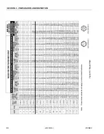
to Figure 3-5., Symbols for these symbols and their 
corresponding functions.

Ground Control Station

ONLY OPERATE FROM THE GROUND CONTROL STATION WITH
PERSONNEL IN THE PLATFORM IN AN EMERGENCY.
FOR PERFORMING AS MANY PRE-OPERATIONAL CHECKS AND
INSPECTIONS FROM GROUND CONTROLS AS POSSIBLE.

NOTE: When machine is shut down for overnight parking or

battery charging, the Emergency Stop switch must
be positioned to OFF to prevent draining the batter-
ies.

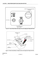
1.

ENABLE SWITCH - On machines built before serial
number 020071522 the enable switch must be
depressed and released before activating the lift
function. A built in timer shuts off power to this func-
tion if it is not activated within 3 seconds after the
enable switch is released. In addition, this timer will
shut off power to the lift function 3 seconds after it is
deactivated, making it necessary to depress and
release the enable switch before activating lift again.
On all machines built after, and including, serial
number 020071522 the enable switch must be
depressed and held for the duration of lift. The
enable switch works in conjunction with the lift
switch only.

NOTE: On machines built before serial 202271522Holding

enable button "IN" while operating lift will cause func-
tion to lift very slow.

2.

PLATFORM/GROUND SELECT SWITCH - A three
position, key operated switch supplies power to plat-
form control console when positioned to platform.
With the switch key held in the ground position,
power is shut off to platform and only ground con-
trols are operable. When released from ground posi-
tion the switch spring returns to the (off) position.

NOTE: With Platform/Ground Select in center position,

power is shut off to controls at both operating sta-
tions.

3.

LIFT SWITCH - A three position, momentary contact
lift control switch provides raising and lowering of
the platform when positioned to up or down.

4.

HOURMETER - The hourmeter indicates the number
of hours the machine has been operated.

5.

BATTERY INDICATOR AND HOURMETER (If
Equipped) -  Provides a visual indication of the con-
dition of the batteries’ charge. The hourmeter to indi-
cate the number of hours the machine has been
operated.

Platform Control Station

1.

ENABLE SWITCH - On machines built before serial
number 020071522 the enable switch must be
depressed and released before activating the drive
and lift functions. A built in timer shuts off power to
these functions if they are not activated within 3 sec-
onds after the enable switch is released. In addition,
this timer will shut off power to the drive and lift func-
tions 3 seconds after they are deactivated, makin git
necessary to depress and release the enable switch
before activating drive or lift again. On all machines
built after, and including, serial number 020071522
the enable switch must be depressed and held for
the duration of lift. The enable switch works in con-
junction with the lift switch only.

2.

EMERGENCY STOP - A two-position red mushroom
shaped switch furnishes power to Platform Controls
when pulled out (on). When pushed in (off), power is
shut down to the platform functions.

3.

TILT ALARM WARNING HORN (If Equipped) - The tilt
alarm warning horn is activated by the tilt alarm
switch when the chassis is on a slope (over 1.5
degrees).

NOTE:

TILT ALARM AND WARNING LIGHT (If Equipped) - A
red warning light on the control console that lights
when the chassis is on a slope (over 1.5 degrees)

.

Updated 3-8-00

Содержание 3369 electric

Страница 1: ...Operators and Safety Manual Model 3369electric 3969electric 3120880 March 8 2000...

Страница 2: ...1111 Fax 065 810122 EUROPEAN OFFICE JLG INDUSTRIES EUROPE Kilmartin Place Tannochside Park Uddingston Scotland G71 5PH Telephone 01698 811005 Main Fax 01698 811055 Parts Fax 01698 811455 CORPORATE OFF...

Страница 3: ...E APPLICATION AND OPERATION PROPER SAFETY PRACTICES ARE THE RESPONSIBILITY OF THE USER AND HIS OPER ATING PERSONNEL ALL INSTRUCTIONS IN THIS MANUAL ARE BASED ON THE USE OF THE MACHINE UNDER PROPER OPE...

Страница 4: ...FOREWORD b JLG Sizzor 3120880 This page left blank intentionally...

Страница 5: ...shall be plainly marked as to their function 4 The controls shall be tested each day prior to use to determine that they are in safe operating condition 5 All personnel in the platform shall at all ti...

Страница 6: ...FOREWORD d JLG Sizzor 3120880 REVISON LOG March 19 1999 Original Issue This manual was part of complete manual 3120597 Pages 3 2 3 5 UpdatedMarch8 2000...

Страница 7: ...E CONTROL 3 1 General 3 1 3 2 Personnel Training 3 1 3 3 Operating Characteristics and Limitations 3 1 3 4 Controls and Indicators 3 2 SECTION 4 MACHINE OPERATION 4 1 Description 4 1 4 2 General 4 1 4...

Страница 8: ...AGE NO 2 1 Daily Walk Around Inspection Sheet 1 of 3 2 4 2 1 Daily Walk Around Inspection Sheet 2 of 3 2 5 2 1 Daily Walk Around Inspection Sheet 3 of 3 2 6 2 2 Lubrication Diagram 2 7 2 3 Torque Char...

Страница 9: ...question on appli cation and or operation JLG Industries should be con sulted MODIFICATION OR ALTERATION OF AN AERIAL PLATFORM SHALL BE MADE ONLY WITH PRIOR WRITTEN PERMISSION OF THE MANUFACTURER 1 2...

Страница 10: ...TION FROM CONTACT WITH OR PROXIMITY TO AN ELECTRICALLY CHARGED CONDUCTOR MAINTAIN A CLEARANCE OF AT LEAST 3 METERS 10 FEET BETWEEN ANY PART OF THE MACHINE OR ITS LOAD AND ANY ELECTRICAL LINE OR APPA R...

Страница 11: ...Y THE OPERA TOR AND HIS SUPERVISOR BEFORE STARTING THE WORK DO NOT OPERATE THIS MACHINE UNLESS IT HAS BEEN SERVICED AND MAINTAINED ACCORDING TO THE MANUFACTURERS SPECIFICATIONS AND SCHEDULE ENSURE DAI...

Страница 12: ...RTERS OR WHEN DRIVING IN REVERSE BE AWARE OF STOPPING DISTANCES WHEN TRAV ELING IN HIGH AND LOW SPEEDS ALWAYS POST A LOOKOUT WHEN DRIVING IN AREAS WHERE VISION IS OBSTRUCTED KEEP NON OPERATING PERSONN...

Страница 13: ...INTER FERING WITH OPERATING CONTROLS AND PER SONS IN THE PLATFORM ENSURE THAT OPERATORS OF OTHER OVERHEAD AND FLOOR LEVEL MACHINES ARE AWARE OF THE AERIAL PLATFORM S PRESENCE DISCONNECT POWER TO OVERH...

Страница 14: ...blished by a qualified person and must be followed to ensure that the machine is safe to operate MODIFICATION OF THE MACHINE WITHOUT CERTIFICATION BY A RESPONSIBLE AUTHORITY THAT THE MACHINE IS AT LEA...

Страница 15: ...ions by a JLG Dealer The following checklist provides a systematic inspection to assist in detecting defective damaged or improperly installed parts The checklist denotes the items to be inspected and...

Страница 16: ...efer to the Lubrica tion Chart for specific requirements 2 5 DAILY FUNCTIONAL CHECK TO AVOID INJURY DO NOT OPERATE A MACHINE UNTIL ALL MALFUNCTIONS HAVE BEEN CORRECTED USE OF A MALFUNC TIONING MACHINE...

Страница 17: ...grease or petroleum jelly 5 When all cables and terminal posts have been cleaned ensure all cables are properly positioned and do not get pinched Close battery compartment cover 6 Start hydraulic syst...

Страница 18: ...SECTION 2 PREPARATION AND INSPECTION 2 4 JLG Sizzor 3120880 Figure 2 1 Daily Walk Around Inspection Sheet 1 of 3...

Страница 19: ...12 Hydraulic Filter No visible damage properly secured no evidence of leakage 13 Hydraulic Reservoir No visible damage or miss ing parts no evidence of leaks Recommended hydraulic fluid level on leve...

Страница 20: ...proper working order 32 Control Console Switches and control lever prop erly secured no loose or missing parts no visible damage placard secure and legible control lever and switches return to neutral...

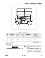
Страница 21: ...requencies must be increased accord ingly Table 2 1 Lubrication Chart INDEX NUMBER COMPONENT NO TYPE LUBE POINTS LUBE METHOD INTERVAL HOURS COMMENTS 1 HydraulicOil FillCap DrainPlug HO KendallHyken 05...

Страница 22: ...SECTION 2 PREPARATION AND INSPECTION 2 8 JLG Sizzor 3120880 Figure 2 3 Torque Chart...

Страница 23: ...the recogni tion and avoidance of potential hazards in the work place with particular attention to the work to be per formed 4 Proper use of all required personnel safety equip ment in particular the...

Страница 24: ...ill cause func tion to lift very slow 2 PLATFORM GROUND SELECT SWITCH A three position key operated switch supplies power to plat form control console when positioned to platform With the switch key h...

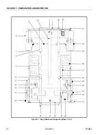
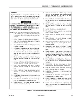
Страница 25: ...BILITIES AND MACHINE CONTROL 3120880 JLG Sizzor 3 3 Figure 3 1 Ground Control Station on Machines Before Serial Number 020071522 Figure 3 2 Platform Control Station on Machines Before Serial Number 02...

Страница 26: ...MACHINE CONTROL 3 4 JLG Sizzor 3120880 Figure 3 3 Ground Control Station on Machines After and Including Serial Number 020071522 Figure 3 4 Platform Control Station on Machines After and Including Ser...

Страница 27: ...vates drive in that direction The thumb operated steer switch on top of the controller handle activates the steer wheels in the direction it is moved Drive speed is determined by distance the controll...

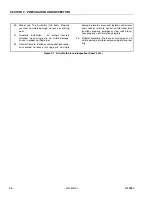
Страница 28: ...SECTION 3 USER RESPONSIBILITIES AND MACHINE CONTROL 3 6 JLG Sizzor 3120880 Figure 3 5 Symbols...

Страница 29: ...SECTION 3 USER RESPONSIBILITIES AND MACHINE CONTROL 3120880 JLG Sizzor 3 7 Figure 3 6 Decal Location Right Side Rear...

Страница 30: ...SECTION 3 USER RESPONSIBILITIES AND MACHINE CONTROL 3 8 JLG Sizzor 3120880 Figure 3 7 Decal Location Left Side Front...

Страница 31: ...are prohibited It must not be used as a forklift crane support for overhead structure or to push or pull another object The JLG Sizzor Lift is powered using a hydraulic pump and cylinders for various...

Страница 32: ...ch and use the handle to retract deck Be sure the latch locks the deck in place after it is retracted Maximum capacity of the deck extension is 227 kg 500 lb 4 6 PLATFORM HANDRAILS FOLD DOWN PROCEDURE...

Страница 33: ...in accordance with instruc tions in Section 2 to ensure readiness for following workday To shut down and park the machine the procedures are as follows 1 Drive machine to a reasonably well protected a...

Страница 34: ...ely tied down to truck or trailer deck Four tie down eyes are pro vided in the frame rail one at each corner of the machine 4 13 MACHINE LIFTING The four slotted holes in the machine frame rails are i...

Страница 35: ...RM WARNING LIGHT A red warning light on the control console that lights when the chassis is on a severe slope over 5 degrees 5 7 TILT ALARM An audible warning horn that will sound when the machine is...

Страница 36: ...SECTION 5 OPTIONAL EQUIPMENT 5 2 JLG Sizzor 3120880 This page left blank intentionally...

Страница 37: ...CH IS FUNCTIONING AND THAT CONTROL INSTRUCTIONS ARE IN PLACE AND LEGIBLE Ground Control Station The Ground Control Station is located on the right side of the frame The controls on this panel provide...

Страница 38: ...els to leave the ground Post Incident Inspection Following any accident thoroughly inspect the machine and test all functions first from the ground controls then from the platform controls Do not lift...

Страница 39: ...SECTION 7 INSPECTION AND REPAIR LOG 3120880 JLG Sizzor 7 1 SECTION 7 INSPECTION AND REPAIR LOG Table 7 1 Inspection and Repair Log Date Comments...

Страница 40: ...SECTION 7 INSPECTION AND REPAIR LOG 7 2 JLG Sizzor 3120880 Table 7 1 Inspection and Repair Log Date Comments...

Страница 41: ...ith regard to the current ownership of JLG Products Please return completed form to the JLG Product Safety Reliability Department via facsimile 717 485 6573 or mail to address as specified on the back...

Страница 42: ......

Страница 43: ......

Страница 44: ...Rua Eng Carlos Stevenson 80 Suite 71 13092 310 Campinas SP Brazil Phone 55 19 3295 0407 Fax 55 19 3295 1025 JLG Europe B V Jupiterstraat 234 2132 HJ Foofddorp The Netherlands Phone 31 23 565 5665 Fax...

Отзывы: