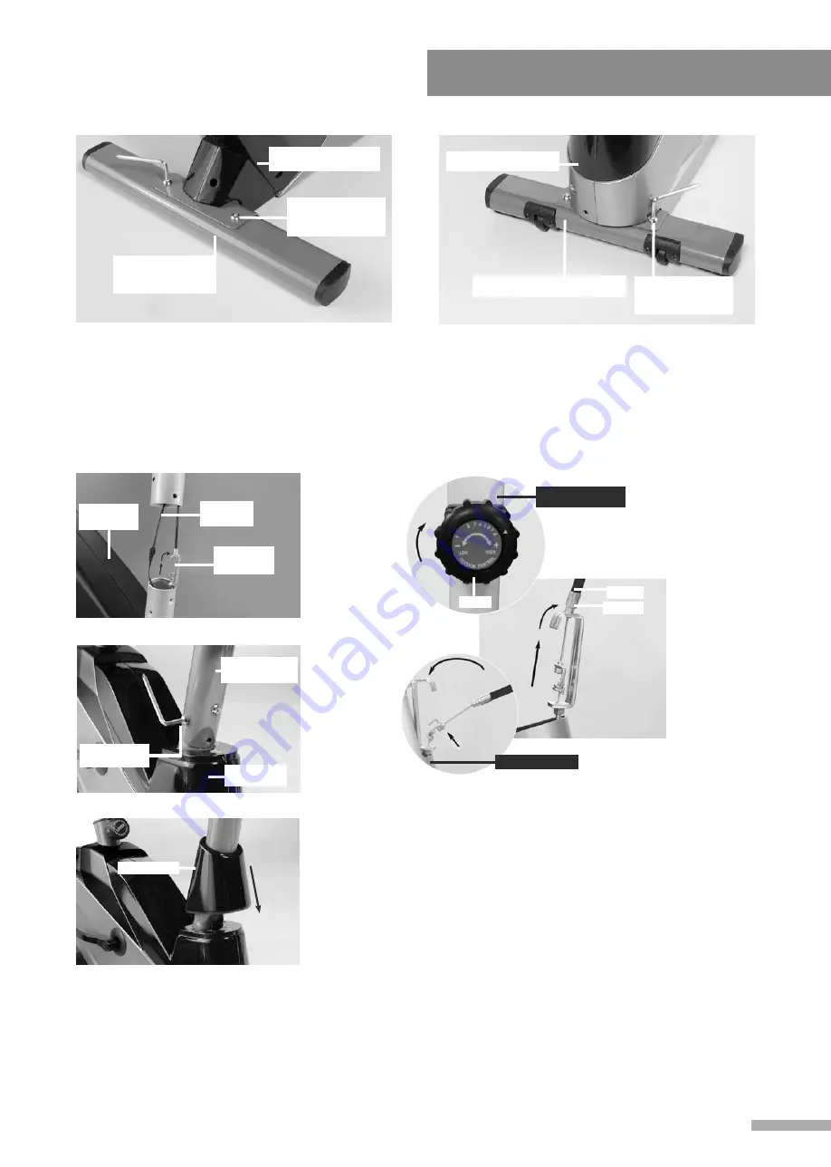
STEP 1.
STEP 2.
REAR
STABILIZER (3)
MAIN FRAME (1)
MAIN FRAME (1)
FRONT STABILIZER (2)
3
Place the Rear Stabilizer (3) under the rear
side of the Main Frame (1). Using 2 Bolts and
2 Washers (A) to fix together as illustrated.
Place the Front Stabilizer (2) under the front
side of the Main Frame (1). Using 2 Bolts and
2 Washers (A) to fix together as illustrated.
Assembly Instruction
BOLT &
WASHER (A)
BOLT &
WASHER (A)
STEP 3.
First, get the Cover (8) goes through Handle Bar Post (4) then connect cables provided from
Handle Bar Post (4) and Main Frame (1). Then have both the stem of the Main Frame (1) and
the Handle Bar Post (4) to be fixed together by means of the Bolts & Washers (B) provided as
illustrated. Then Pull down the cover and connect it with Main Frame (1) Cover (8).
MAIN
FRAME (1)
SENSOR
CABLE
TENSION
CABLE
MAIN
FRAME (1)
COVER (8)
HANDLE BAR
POST (4)
BOLTS&
WASHER (B)
FRAME(1)
CABLE
SPACER
A
B
KNOB
FRONT POST(2)
MAIN FRAME(1)
1. Turn the tension knob fixed on the Front Post (2) to level 8.
2. Slide the head of top cable from Front Post (2) into the opening
end of the hook of another bottom cable from Main Frame (1) as
shown on photo A.
3. Pull and stretch the top cable up and slide the spacer into the
top opening then place it at the top of U-shapeed brace as shown
on photo B.
Tension Cable assembly
Содержание Surge 7009
Страница 1: ...MAGNETIC BIKE Surge 7009...
Страница 10: ...Exploded Drawing D 21A 21B 21 27A 30 38B 17A 17 20 47 18 20A 19 48 8...
Страница 12: ......


