background image


User’s Manual


1.3.5 Power Consumption 

Input Voltage:


DC 12~24V, 4-pin connector 

Power Consumption: 

TDP


12V/1.35A (Intel® J1900 1.6GHz+4GB DDR3L)


Power Adapter:


AC to DC 12V/5A, 60 W 

Power Requirement:

 Minimum power input: DC 12V/1.8A 

1.4 Environmental Specifications 

Operating temperature:


-10 ~ 55° C (Wide operating temperature mSATA/SSD)   

0 ~ 50° C (Conventional operating temperature SSD&HDD) 

Relative humidity: 

10~95% @ 40°C (non-condensing) 

Storage temperature: 

-20 ~ 60°C (-4 ~ 140°F) 

Vibration loading during operation:


With HDD: 1Grms, IEC 60068-2-64, random, 5 ~ 500 Hz, 1hr/axis 

Shock during operation: 

With HDD: 10G, IEC 60068-2-27, half sine, 11ms duration 

EMC: 

CE, FCC Class A 

1.5 Mechanical Specifications 

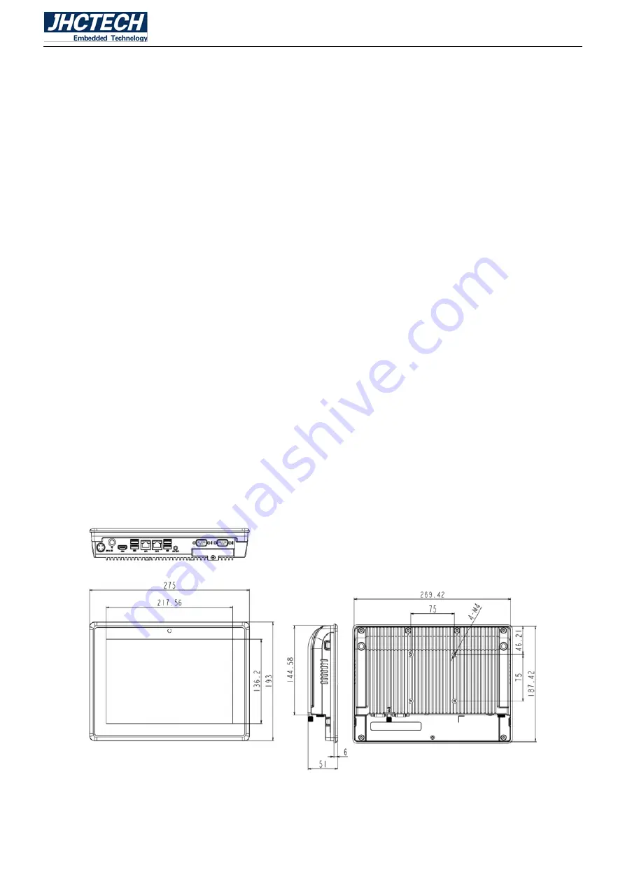
ALAD-A1001T Dimension:


Unit: mm


Figure 1.1


Содержание ALAD-A1001T

Страница 1: ...User s Manual 1 ALAD A1001T User s Manual ...

Страница 2: ...User s Manual 2 Version Note No Ver Note Date Writer 1 A1 0 First edition 20170916 Colin Cheng 2 A1 1 Second version 20180910 Tracy Liu 2 A1 2 COM1 2 485 signal correction 20200824 Echo Guo ...

Страница 3: ... to be accurate and reliable However Shenzhen JHC Technology Co Ltd assumes no responsibility for its use nor for any infringements of the rights of third parties which may result from its use Acknowledgements Award is a trademark of Award Software International Inc IBM PC AT PS 2 and VGA are trademarks of International Business Machines Corporation Intel and Pentium are trademarks of Intel Corpor...

Страница 4: ...ent materials service time and freight Please consult your dealer for more details If you think you have a defective product follow these steps 1 Collect all the information about the problem encountered For example CPU speed JHC products used other hardware and software used etc Note anything abnormal and list any onscreen messages you get when the problem occurs 2 Call your dealer and describe t...

Страница 5: ...ce when the equipment is operated in a commercial environment This equipment generates uses and can radiate radio frequency energy and if not installed and used in accordance with the instruction manual may cause harmful interference to radio communications Operation of this equipment in a residential area is likely to cause harmful interference in which case the user will be required to correct t...

Страница 6: ...lect 10 2 3 3 AT ATX Power on mode setting 10 2 3 4 JC1 COM2 RS232 R485 R422 Mode Select 11 2 3 5 JLV LVDS 12V 5V 3 3V Power supply select 12 2 4 I O indication 13 2 4 1 Ethernet Connector LAN 13 2 4 2 Power Input Connector DC IN 14 2 4 3 USB Connector 14 2 4 4 COM1 2 Connector 15 2 4 5 SATA3 0 Serial ATA Connector 16 2 4 6 SATA Serial ATA Power Connector 17 2 5 Installation 17 2 5 1 HDD SSD Insta...

Страница 7: ...User s Manual 1 General Information CHAPTER 1 ...

Страница 8: ... design 2 10 1 LED TFT LCD capacitive resistive touch 3 Intel Baytail D Celeron J1900 CPU 4 1 DDR3L 1333 SODIMM Up to 8GB 5 1 Mini PCIe PCIeX1 USB 6 2 COM 2 LAN 1 USB3 0 3 USB2 0 2 2W Speaker 7 1 2 5 HDD Bay 1 mSATA dual storage 8 DC 9 24V power input 9 Easy pluggable SATA bay 1 3 Specifications 1 3 1 General CPU Intel Baytail D family Celeron J1900 2 0 2 24GHz 4C4T TDP 10W BIOS SPI 8MB flash ROM ...

Страница 9: ...Temperature 20 70 Back light lifetime 15 000 hours S00X 50 000 hours T00X TOUCH Type 5 wire resistive touch Projected capacitive touch Resolution Gap less Gap less Light transmittance 83 90 Interface USB USB Power Consumption 5 V 200 mA 5 V 300 mA OS Windows and Linux Windows and Linux Click Lifetime 15 million times 3000 million times 1 3 3 Ethernet Chipset Intel I211AT PCI express gigabit ethern...

Страница 10: ...ions Operating temperature 10 55 C Wide operating temperature mSATA SSD 0 50 C Conventional operating temperature SSD HDD Relative humidity 10 95 40 C non condensing Storage temperature 20 60 C 4 140 F Vibration loading during operation With HDD 1Grms IEC 60068 2 64 random 5 500 Hz 1hr axis Shock during operation With HDD 10G IEC 60068 2 27 half sine 11ms duration EMC CE FCC Class A 1 5 Mechanical...

Страница 11: ...User s Manual 5 Hardware Installation CHAPTER 2 ...

Страница 12: ...14 that is housed in an aluminum plate chassis Your HDD and SDRAM are all readily accessible by removing the aluminum cover Any maintenance or hardware upgrades can be easily completed after opening the chassis Warning Do not remove any mechanical parts until you have verified that no power is flowing within the Embedded Panel Computer Power must be switched off and the power cord must be unplugge...

Страница 13: ...electrical switch It consists of two metal pins and a small metal clip often protected by a plastic cover that slides over the pins to connect them To close a jumper you connect the pins with the clip To open a jumper you remove the clip Sometimes a jumper will have three pins labeled 1 2 and 3 In this case you would connect either pins 1 and 2 or pins 2 and 3 Figure 2 3 The jumper settings are sc...

Страница 14: ...tact your local distributor or sales representative before you make any changes 2 3 Jumper Location The ALAD A1001T Embedded Panel Computer has a number of jumpers inside the chassis that allows you to configure your system to suit your application The table below lists the functions of the various jumpers The table below shows the function of each of the board s jumpers Figure 2 5 ...

Страница 15: ...S data Setting Figure 2 6 If you encounter the followings a CMOS data becomes corrupted b You forgot the supervisor or user password you can reconfigure the system with the default values stored in the ROM BIOS To load the default values stored in the ROM BIOS please follow the steps below 1 Power off the system and unplug the power cord 2 Set JCMOS pins 2 and 3 to On Wait for a few seconds and se...

Страница 16: ...User s Manual 10 2 3 2 USB_PWR1 USB_PWR2 USB1 USB2 Power Select Figure 2 7 2 3 3 AT ATX Power on mode setting Figure 2 8 ...

Страница 17: ...mes in connect pins 2 and 3 of the jumper If you want to use the power button connect pins 1 and 2 of AT ATX When using AT ATX Power On feature to power the system back on after a power failure occurs the system may not power on if the power lost is resumed within 5 seconds power flicker 2 3 4 JC1 COM2 RS232 R485 R422 Mode Select Figure 2 9 ...

Страница 18: ...re powering on the system make sure that the power settings of JP8 match the LCD panel s specification Selecting the incorrect voltage will seriously damage the LCD panel Tip In addition to setting jump cap also involves hardware changes For detailed information please contact with local distributors dealers or contact and sincere customer service ...

Страница 19: ... ALAD A1001T is equipped with two Intel I211AT chips for 10 100 1000Mbps Ethernet controllers The Ethernet port provides a standard RJ 45 connector with LED indicators on the front side to show its Active Link status Green LED and Speed status white LED Table 2 1 for pin assignments Figure 2 13 Ethernet Connector ...

Страница 20: ...4 pin MicroTCA DC IN 9 24V Figure 2 14 4 pin MicroTCA Table 2 2 Power Connector Pin Assignments Pin Signal Name 1 9 24V 2 9 24V 3 GND 4 GND 2 4 3 USB Connector The USB device allows data exchange between your computer and a wide range of simultaneously accessible external Plug and Play peripherals The ECM I714 board is equipped with one USB 3 0 port USB 1 three USB 2 0 ports USB 2 3 4 3 USB2 0 por...

Страница 21: ...USB3 0 Port Pin Assignments Pin Signal Name 1 VBUS 2 D 3 D 4 GND 5 StdA_SSRX 6 StdA_SSRX 7 GND_DRAIN 8 StdA_SSTX 9 StdA_SSTX Shell Shield 2 4 4 COM1 2 Connector COM 1 and COM 2 are D sub 9 pin connectors COM1 is RS232 COM2 can be configured as RS232 RS422 RS485 by Jumper setting The serial ports are asynchronous communication ports with 16C550A compatible UARTs that can be used with modems serial ...

Страница 22: ...NC 4 DTR RX NC 5 GND GND GND 6 DSR NC NC 7 RTS NC NC 8 CTS NC NC 9 RI NC NC 2 4 5 SATA2 0 Serial ATA Connector The ALAD A1001T contains a Serial ATA 2 0 port with data transfer rate up to 3Gb s The Serial ATA connector is used to connect Serial ATA devices Figure 2 18 SATA2 0 Connector Table 2 6 SATA Pin Assignments Pin Signal Name Pin Signal Name 1 GND 5 RXN 2 TXP 6 RXP 3 TXN 7 GND 4 GND ...

Страница 23: ...tor Which used to provide 5V 12V power for SATA devices Figure 2 19 SATA Power Connector Table 2 7 SATA Power Pin Assignments Pin Signal Name 1 DC 12V 2 GND 3 GND 4 DC 5V 2 5 Installation 2 5 1 HDD SSD Installation Step 1 Unscrew 1 screw on the HDD cover and open the HDD cover Figure 2 20 ...

Страница 24: ...User s Manual 18 Figure 2 21 Step 2 Screw the HDD SSD on the drive bay though 4 screws Figure 2 22 Step 3 Push the drive bay into the SATA connector and screw 1 screw to lock drive bay Figure 2 23 ...

Страница 25: ...9 2 5 2 Installing SODIMM module Step 1 Unscrew the 9 screws on the back chassis and open the back chassis Figure 2 24 Figure 2 25 Step 2 Pull out 4 cable connectors from front IO card touch panel and LCD Figure 2 26 ...

Страница 26: ... 30 degrees angle into the socket Push down the module until the clips at each end of the socket lock into position Figure 2 27 Figure 2 28 Step 4 Connect 4 cable connectors into front IO card touch panel and LCD Figure 2 29 Step 5 Close the chassis back to the front panel and screw the 9 screws on the chassis ...

Страница 27: ...ure 2 30 2 5 3 Installing mSATA Flash Card module Step 1 Unscrew the 9 screws on the back chassis and open the back chassis Figure 2 31 Figure 2 32 Step 2 Pull out 4 cable connectors from front IO card touch panel and LCD ...

Страница 28: ...its notch aligned with the socket of the board and insert it at a 30 degrees angle into the socket screw 1 screws to the holder as shown in the following picture Figure 2 34 Figure 2 35 Step 4 Connect 4 cable connectors into front IO card touch panel and LCD ...

Страница 29: ...e chassis back to the front panel and screw the 9 screws on the chassis Figure 2 37 2 5 4 Panel Mounting Step 1 Install the panel PC into the panel opening Figure 2 38 Step 2 Pull out the 4 clamps from the holes around the two sides of the bezel ...

Страница 30: ...User s Manual 24 Figure 2 39 Figure 2 40 Step 3 Insert the screws into each clamp and fasten them Figure 2 41 Figure 2 42 ...

Страница 31: ...User s Manual 25 Driver Installation CHAPTER 3 ...

Страница 32: ...formation that is not included in this manual Never try to install all software from folder that is not specified for use with your motherboard 4 2 Auto installing under Windows 8 The Auto install DVD ROM CD ROM makes it easy for you to install the drivers and software for your motherboard If the Auto install DVD ROM CD ROM does not work on your system you can still install drivers through the fil...

Страница 33: ...r different operating systems such as Windows 7 8 Always go to the correct folder for the kind of OS you are using In install the software execute a file named SETUP EXE by double clicking the file and then following the instructions on the screen The Exit button closes the Auto Setup window Utilities Tab Lists the software utilities that are available on the disk Information Tab Displays the path...

Страница 34: ...ars Figure 4 2 5 Follow the instructions on the screen to install the items Drivers and software are automatically installed in sequence Follow the onscreen instructions confirm commands and allow the computer to restart a few times to complete the installation Windows 8 will show the following screen after system restart you must select Desktop in the bottom left to install the next driver ...

Страница 35: ...ue this process to complete the driver installation Figure 4 4 4 3 Manual Installation Insert the disk in the DVD ROM CD ROM drive and locate the PATH DOC file in the root directory This file contains the information needed to locate the drivers for your motherboard Look for the chipset and motherboard model then browse to the directory and path to begin installing the ...

Страница 36: ...he readme text file README TXT or README DOC for information on installing the driver or software for your operating system 4 4 Utility Software Reference All the utility software available from this page is Windows compliant They are provided only for the convenience of the customer The following software is furnished under license and may only be used or copied in accordance with the terms of th...

Отзывы: