


32
OnChip IDE Channal0/Channel1
The integrated peripheral controller contains an IDE interface with support for two IDE
channels. Select
Enabled
to activate each channel separately. The settings are: Enabled and
Disabled.
Primary/Secondary Master/Slave PIO
The four IDE PIO (Programmed Input/Output) fields let you set a PIO mode (0-4) for each of
the four IDE devices that the onboard IDE interface supports. Modes 0 through 4 provide
successively increased performance. In Auto mode, the system automatically determines the
best mode for each device. The settings are: Auto, Mode 0, Mode 1, Mode 2, Mode 3, Mode
4.
Primary/Secondary Master/Slave UDMA
Ultra DMA/33 implementation is possible only if your IDE hard drive supports it and the
operating environment includes a DMA driver (Windows 95 OSR2 or a third-party IDE bus
master driver). If your hard drive and your system software both support Ultra DMA
33/66/100, select Auto to enable BIOS support. The settings are: Auto, Disabled.
IDE HDD Block Mode
Block mode is also called block transfer, multiple commands, or multiple sector read/write. If
your IDE hard drive supports block mode (most new drives do), select Enabled for automatic
detection of the optimal number of block read/writes per sector the drive can support. The
settings are: Enabled, Disabled.
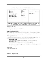
3-7-2 OnChip SIO Function
CMOS Setup Utility – Copyright(C) 1984-2000 Award Software
OnChip SIO Function
Item Help
Onboard FDD Controller Enabled
Onboard Serial Port 1 Auto
Onboard Serial Port 2 Auto
UART 2 Mode Normal
IR Duplex Mode Half
TX,RX inverting enable No, Yes
Onboard Parallel Port 378/IRQ7
Onboard Parallel Mode Normal
Parallel Port EPP Type EPP1.9
ECP Mode Use DMA 3
Menu Level >>
↑↓→←
Move Enter:Select Item +/-/PU/PD:Value F10:Save ESC:Exit F1:General Help
F5:Previous Values F6:Optimized Defaults F7:Standard Defaults


