9
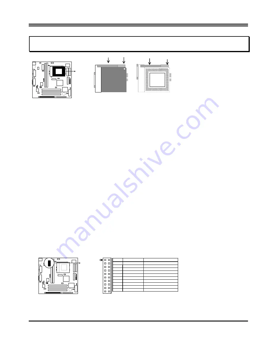
IMPORTANT: You must set jumpers JP10,JP11 “CPU Type selector” on
page 6
and jumper JP9 “CPU
Voltage Selection” on
page 6
depending on the CPU that you install.
CPU ZIF Socket 7
So
cket 7
Lock
Blank
Lever White Dot
So
cket 7
CPU
2-5 Expansion Cards
First read your expansion card documentation on any hardware and software settings that may be
required to setup your specific card.
Installation Procedure:
1. Read the documentation for your expansion card.
2. Set any necessary jumpers on your expansion card.
3. Remove your computer’s cover.
4. Remove the bracket on the slot you intend to use.
5. Carefully align the card’s connectors and press firmly.
6. Secure the card on the slot with the screw you remove in step 4.
7. Replace the computer’s cover.
8. Setup the BIOS if necessary.
9. Install the necessary software drivers for your expansion card.
2-6 External Connectors
1. ATX Power Connector (20-pins block): PW1
ATX Power Supply connector. This is a new defined 20-pin connector that usually comes with ATX case.
The ATX Power Supply allows to use soft power on momentary switch that connect from the front panel
switch to 2-pin Power On jumper pole on the motherboard. When the power switch on the back of the ATX
power supply turned on, the full power will not come into the system board until the front panel switch is
momentarily pressed. Press this switch again will turn off the power to the system board.
( * Please wait
aleast 4sec , when turn off and turn on the power .)
Pi
n 1
PIN
ROW2
ROW1
1
3.3V
3.3V
2
-12V
3.3V
3
GND
GND
4
Soft Power On
5V
5
GND
GND
6
GND
5V
7
GND
GND
8
-5V
Power OK
9
+5V
+5VSB(for Soft Logic)
10
+5V
+12V
2. PS/2 Mouse & PS/2 Keyboard Connector: KBMS1


