8
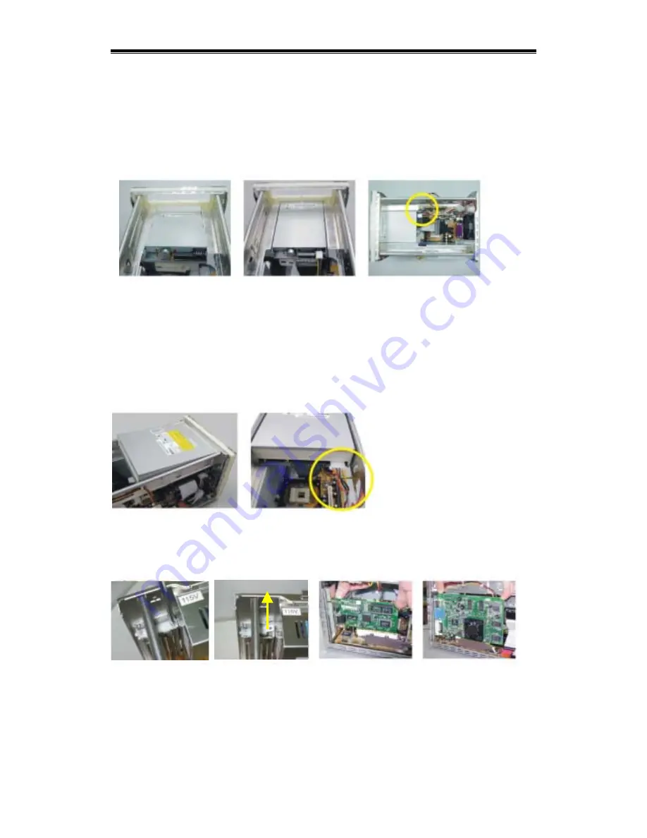
Installing 3.5” Device
Hold the 3.5” device from the back and place it down from the top of the case to fit in the position
with device bezel down for smooth operation. Lower the tail part that you are holding to level and
push forward to align the mounting holes on 3.5” device with the case mounting holes. Screw to
fix it in place. Connect FDD cable from FDD1 connector on motherboard to FDD. Make sure the
red stripe of the cable is aligned to pin 1 of connector. Insert firmly to insure the contact.
Connect the small 4-pin power connector to the FDD. (Refer to the instruction of the respective
device If other 3.5” device is installed).
Installing 5.25” IDE Optical Device
Hold the optical device from the back and place it down from the top of the case with device
bezel tilting down to contact the 5.25” cavity. Lower the tail part that you are holding to level and
push forward to align the mounting holes of optical device with case mounting holes. Tighten the
screw to fix the device in place. You might need to adjust forward or backward to locate the
appropriate horizontal position of the optical device. (Please refer to Important Notice section).
Connect IDE cable from IDE2 connector on motherboard to optical device. Make sure the red
stripe of the cable is aligned to Pin 1 of connector. Insert firmly to insure the contact. Locate the
cable clip on the outside on HDD bracket and clip the IDE cable onto it. Connect power cable to
the device.
Installing Expansion Card
Remove the expansion card bracket on the back of the case by unscrewing the bracket holding
plate on top of it. Plug in the expansion card vertically down firmly to its end position. Screw the
bracket holding plate back to firmly to fix the expansion card bracket in position.
Completing Installation
Put back the top cover gently and tighten the thumbscrews to complete the installation. You are
now ready to explore the feature-rich system.
Содержание 2USER-QIG-MINIQ-R1.1
Страница 1: ...Quick Installation Guide Rev 1 1 G03 MQ2R2...


