


16
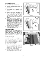
Outfeed Roller Height
1. Disconnect machine from power source.
2. Make sure the knives are set properly as
previously explained under "Knife
Adjustment."
3. Place the gauge block (F, Figure 25) on the
table directly beneath the cutterhead (D,
Figure 25).
4. Using a 0.02" (0.5mm) feeler gauge (G,
Figure 25) placed on top of the gauge block,
raise the work table until the knife just
touches the feeler gauge when the knife is
at its lowest point. Do not move the work
table any farther until the outfeed roller is
adjusted.
5. Remove the feeler gauge and move the
gauge block (F, Figure 25) under one end of
the outfeed roller. The bottom of the outfeed
roller should just touch the top of the gauge
block. If an adjustment to the outfeed roller
is necessary, loosen the lock nut (J, Figure
26) and turn screw (H, Figure 26) until the
outfeed roller just touches the gauge block.
Then tighten lock nut (J, Figure 26).
6. Check and adjust the opposite end of the
outfeed roller in the same manner.
Infeed Roller Height
Use the exact same procedure for checking the
infeed roller as you did for the outfeed roller,
Use the .02" (0.5mm) feeler gauge atop the
gauge block. If adjustment is necessary, use the
lock nut and screw on each end of the infeed
roller.
Chipbreaker Height
The chipbreaker breaks off the larger chips
before the stock reaches the cutterhead. Use the
gauge block and a .02" (0.5mm) feeler gauge to
check the height of the chipbreaker, following
the same procedure as explained in the previous
sections. If adjustment is needed:
1. Remove top cover of planer.
2. Loosen the lock nuts (A, Figure 27) at both
ends of the chipbreaker, and turn the set
screws (B, Figure 27) to raise or lower the
chipbreaker as needed. The set screws
should be turned the same amount.
3. When the chipbreaker contacts the gauge
block, tighten both lock nuts (A, Figure 27).
Figure 25
Figure 26
Figure 27
Содержание JWP-15DX
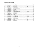
Страница 23: ...23 Head Assembly ...
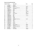
Страница 26: ...26 Base Assembly ...
Страница 28: ...28 Table Assembly ...
Страница 30: ...30 Gear Box Assembly ...
Страница 32: ...32 Stand and Motor Assembly ...
Страница 34: ...34 Electrical Connections ...
Страница 35: ...35 ...
Страница 36: ...36 WMH Tool Group 2420 Vantage Drive Elgin Illinois 60124 Phone 800 274 6848 www wmhtoolgroup com ...


