


12
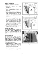
Table Rollers
Your planer is supplied with two table rollers
(Figure 14) which turn as the stock is fed into the
machine, thus reducing friction. It is not possible
to give exact dimensions on the proper height
setting of the table rollers because each type of
wood behaves differently. As a general rule,
however, when planing rough stock the table
rollers should be set at high position. When
planing smooth stock the rollers should be set at
low position.
NOTE: When raising the roller higher above the
table, the range is from zero to 0.06" (Figure 15).
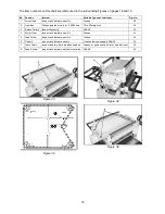
The table rollers are factory set for average
planing and are parallel to the table surface. If
you desire to adjust the table rollers higher or
lower, proceed as follows:
1. Disconnect machine from power source.
2. Lay a straight edge across both rollers.
3. On one side of the table, loosen the set
screws (A, Figure 14) with a 3mm hex
wrench, and turn the eccentric shafts (B,
Figure 14) to raise or lower the rollers.
4. When proper height is achieved, tighten set
screws.
5. Adjust the rollers from the opposite side of
the table in the same manner.
IMPORTANT: Be sure that the height of front
and rear rollers are the same. And the table
rollers must always be set parallel to the table.
Cutterhead
Although your planer was carefully adjusted at
the factory, it should be checked before being
put into operation. Any inaccuracies due to
rough handling in transit can be corrected by
following the directions in this manual.
To check the adjustments you will need feeler
gauges, and a home-made gauge block made of
hardwood. This gauge block can be made by
following the dimensions shown in Figure 16.
Installing and Replacing Knives
Use caution and proceed
slowly when working with and around the
knives – they are extremely sharp.
The planer knives are double-sided. If one side
becomes dull, the knife can simply be rotated to
use the new edge. When both edges have
become worn, the knife must be replaced.
Figure 14
Figure 15
Figure 16
Содержание JWP-15DX
Страница 23: ...23 Head Assembly ...
Страница 26: ...26 Base Assembly ...
Страница 28: ...28 Table Assembly ...
Страница 30: ...30 Gear Box Assembly ...
Страница 32: ...32 Stand and Motor Assembly ...
Страница 34: ...34 Electrical Connections ...
Страница 35: ...35 ...
Страница 36: ...36 WMH Tool Group 2420 Vantage Drive Elgin Illinois 60124 Phone 800 274 6848 www wmhtoolgroup com ...


