
6
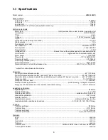
5.0
Specifications
Model number ......................................................................................................................................
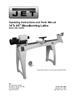
JWL-1440VS
Stock numbers
:
Lathe with Leg Set ................................................................................................................................. 719400K
Lathe
only
................................................................................................................................................ 719400
Leg Set only ............................................................................................................................................. 719402
Bed Extension 20”, with tool post (optional accessory) ............................................................................... 719401
Motor and electricals:
Motor type ............................................................................ totally enclosed fan cooled, induction, capacitor start
Horsepower
................................................................................................................................. 1HP (0.746 kW)
Phase......................................................................................................................................................... single
Voltage
........................................................................................................................ 115/230V (prewired 115V)
Cycle
........................................................................................................................................................... 60Hz
Listed FLA (full load amps 115V/230V) .................................................................................................... 11/5.5 A
Starting
amps
............................................................................................................................................... 10 A
Running amps (no load) ............................................................................................................................... 6.6 A
Start
capacitor
......................................................................................................................... 200MFD, 125VAC
Run
capacitor
................................................................................................................................ 30
μ
F, 250VAC
Power
transfer
............................................................................................................................................ V-belt
Variable drive ............................................................. Reeves Drive, with variable speed within established range
On/off switch ........................................................................................... toggle switch with removable safety key
Motor
speed
........................................................................................................................................ 1720 RPM
Power
cord
............................................................................................................................ 3/C 16 AWG (300V)
Power
cord
length
............................................................................................................................. 6 ft. (183cm)
Power plug installed (115V) ................................................................................................................... 5-15P UL
Power
requirements
.......................................................................................................................... single phase
Recommended circuit and fuse/breaker size
1
............................................................... 20A (115V), or 15A (230V)
1
subject to local/national electrical codes.
Capacities:
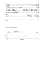
Working distance between centers .................................................................................................. 40” (1016mm)
Working distance between centers, optional 20” bed ext. mounted ............................................. 60-3/4” (1543mm)
Maximum distance between spindle face and tailstock quill, optional 20” bed ext. mounted ......... 62-1/2” (1587mm)
Swing
over
bed
........................................................................................................................... 14-1/2” (370mm)
Swing over tool rest base ..................................................................................................................11” (280mm)
Number of indexing positions ..................................................................... positive locking, 10 degree increments
Swing over 20” bed extension in low position
(optional accessory)
.............................................. 32-1/2” (826 mm)
Headstock and Spindle:
Spindle
taper
......................................................................................................................................... #2 Morse
Spindle thread size ............................................................................................................................... 1” x 8 TPI
Spindle speed (RPM) ...................................................................................................variable within 400 to 3000
Headstock
spindle
bore......................................................................................................................3/8” (10mm)
Spindle
direction
....................................................................................................................................... forward
Headstock
movement
...............................................................................................
sliding
and 360 deg. rotation
Headstock rotation positive lock positions ............................................................ 0, 30, 60, 90, 120, 180, 270 deg.
Tailstock:
Tailstock quill taper ................................................................................................................................ #2 Morse
Tailstock
bore
....................................................................................................................................5/16” (9mm)
Tailstock quill travel ...................................................................................................................... 4-1/4” (108mm)
Tailstock quill thread ......................................................................................................... acme, 5/8-11UNC (LH)
Materials:
Legs
....................................................................................................................................................... cast iron
Bed
........................................................................................................................................................ cast iron
Headstock
.............................................................................................................................................. cast iron
Tailstock
................................................................................................................................................. cast iron
Tailstock
quill
................................................................................
hardened
HRC20 steel, with laser etched scale
Tool support and base ............................................................................................................................ cast iron
Содержание JWL-1440VS
Страница 28: ...28 16 2 1 JWL 1440VS Bed Assembly Exploded View...
Страница 32: ...32 17 0 Electrical Connections...


