11
and any unusual sizes of workpieces that might
extend off the machine’s table.
9. When the machine is over its anchors, level the
machine using shims under the corners
needing them. The machinist’s level used for
leveling should be placed on the table. The
table is the reference surface for both side-to-
side and fore-and-aft leveling. Be certain you
get it level in BOTH directions.
Mill must be supported equally
under all four corners. Failure to comply may
cause the column to twist and put a bind in the
table ways.
10. When machine is level, secure base to the
anchor system.
IMPORTANT:
Before attempting to raise mill
head, refer to
section 10.1
for procedures to
safely raise and set up the mill head.
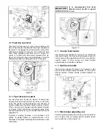
11. Loosen the four hex head nuts (see A, Figure
18) about 1/4 turn each (counterclockwise), just
enough to allow rotation of head.
12. While assisting the worm mechanism by putting
upward pressure on the motor by hand, use the
supplied wrench to turn worm nut and raise
head to upright position.
13. Tighten the head bolts slightly — not torqued —
just snug.
14. Using mineral spirits or other cleaning solvent,
clean all of the rust proofing from where it may
have been applied. This is important; moving
the table or any other components before
removing the rust proofing will only put rust
proofing where you don’t want it.
Some of the following steps may have already been
performed on the machine. If so, ignore the
instructions related to those particular steps.
Otherwise, perform them in the order listed. Refer to
Figure 3 to help locate items.
15. Install the table longitudinal and cross-feed
cranks on their respective shafts using the nuts
on the shafts to secure the cranks.
16. Remove any rust proofing from the drawbar and
its spacer, and put drawbar with spacer
installed into spindle center through top of
machine.
17. Slide the fine feed handwheel over the
handwheel hub and push it back until its roll pin
engages the hole in the hub and the wheel is
flush with the hub surface.
18. Put the coarse feed handle on the feed shaft
and tap it lightly until its roll pin engages a hole
in the hub and it is flush against the hub surface.
19. Unwrap and clean the knee crank and install it
on its shaft.
20. Install the rubber way covers at front and behind
the table.
7.0
Electrical connections
All electrical connections must
be made by a qualified electrician! Failure to
comply may cause serious injury!
7.1
General electrical cautions
This machine must be grounded in accordance with
the National Electrical Code and local codes and
ordinances. This work should be done by a qualified
electrician. The machine must be grounded to
protect the user from electrical shock.
7.2
Wire sizes
For circuits which are far away
from the electrical service box, the wire size
must be increased in order to deliver ample
voltage to the motor.
To minimize power losses and to prevent motor
overheating and burnout, the use of wire sizes for
branch circuits or electrical extension cords
according to the following table is recommended:
Conductor
Length
AWG Number
230 Volt Lines
0 – 50 Ft.
No. 14
50 – 100 Ft.
No. 14
Over 100 Ft.
No. 12
Table 1
Confirm that power at the site matches power
requirements of the mill before connecting to the
power source.
The JTM-949EVS/230 and JTM-1050EVS2 have
been pre-wired for 230 volt operation only.
Before connecting to power source, make sure that
switch is in OFF position.
The mill must be properly grounded.
Check for proper spindle rotation
in the high-speed
range
. The spindle should rotate clockwise when
viewed from top of machine. If spindle rotates
counter-clockwise, disconnect from power and
switch two of the three power leads.
Содержание JTM-1050EVS2
Страница 9: ...9 5 2 Overview and terminology JTM 949EVS 230 JTM 1050EVS2 Figure 2 Overview JTM 949EVS 230 shown ...
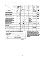
Страница 13: ...13 9 3 Control positions for milling and drilling operations Table 2 ...
Страница 23: ...23 13 1 1 JTM 949EVS JTM 1050EVS2 Upper Head Assembly Exploded View ...
Страница 26: ...26 13 2 1 JTM 949EVS JTM 1050EVS2 Lower Head Assembly Exploded View ...
Страница 30: ...30 13 3 1 JTM 949EVS Base Machine Exploded View ...
Страница 33: ...33 13 4 1 JTM 1050EVS2 Base Machine Exploded View ...
Страница 36: ...36 13 5 1 JTM 949EVS Table Assembly Exploded View ...
Страница 38: ...38 13 6 1 JTM 1050EVS2 Table Assembly Exploded View ...
Страница 46: ...46 14 0 Electrical Connections JTM 949EVS JTM 1050EVS2 ...
Страница 47: ...47 This page intentionally left blank ...
Страница 48: ...48 427 New Sanford Road LaVergne Tennessee 37086 Phone 800 274 6848 www jettools com ...


