12
3. Rotate scale
counterclockwise
all the way until
it stops at “0”.
4. Loosen lock handle (A
2
).
5. Use feed handle (B, Figure 8-1) to lower bit to
desired depth based on reference mark.
6. Hold feed handle in position, and tighten lock
handle (A
2
).
7. The bit will now stop at the marked depth
when feed handle is rotated.
8. To release depth stop, loosen lock handle (A
2
).
8.5
Powerfeed operation
See Figures 8-1 and 8-2.
1. Select appropriate spindle speed range (lever
C on clutch model; reposition belt on step
pulley model).
2. Select downfeed rate (D).
3. Set depth of cut (
sect. 8.4
).
4. Tighten handle (A
2
) to secure setting.
5. Loosen powerfeed locking knob (E).
6. Turn on spindle and adjust speed knob (H) to
desired RPM.
7. Pull feed handle (B) outward (away from head)
to engage powerfeed.
8. Once downfeed has reached pre-set depth,
the trip will release and spindle will retract.
9. To stop feed before cycle has ended, push
feed handle (B) toward head.
NOTE: Set downfeed dial (D) to “0” when not using
powerfeed.
8.6
Quill retraction lock
The quill can be held in the down position and
prevented from retracting, to facilitate removal of
chuck arbor or for cleaning.
1. Loosen lock handle (A
2
, Figure 8-1).
2. Rotate feed handle (B) to lower spindle to
point at which it is to be locked, and hold feed
handle stationary in this position.
3. Rotate scale (A
1
)
clockwise
all the way until it
stops.
4. Tighten lock handle (A
2
). You can now release
downfeed handle. The quill will remain in this
lowered position until released.
5. To release quill, loosen lock handle (A
2
).
8.7
Drilling recommendations
The following are only general recommendations.
Consult a machinery handbook or contact the
specific tool manufacturer for more detailed
information.
8.7.1
Drilling speeds
The speed of a drill is usually measured in terms of
the rate at which the outer periphery of the tool
moves in relation to the work being drilled. The
common term for this is Surface Feet per Minute
(SFM). The relationship of SFM is expressed in the
following formulas:
SFM = 0.26 X rpm X Drill Diameter (in inches)
RPM = 3.8 x ________SFM__________
Drill diameter (in inches)
In general, the higher the speed the shorter the drill
life. Operating at the low end of the speed range
for a particular material will result in longer life. The
most efficient speed for drill operation depends
upon many variables:
1. Composition and hardness of material.
2. Depth of hole.
3. Efficiency of cutting fluid.
4. Type and condition of drilling machine.
5. Desired quality of hole.
6. Difficulty of set-up.
8.7.2
Drilling feed
The feed of a drill is governed by size of tool and
the material drilled. Because feed rate partially
determines rate of production and also is a factor in
tool life, it should be chosen carefully for each job.
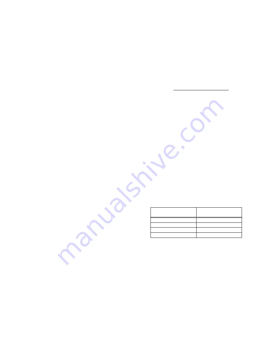
In general, the most effective feeds will be found in
the following ranges:
Diameter of Drill
(inches)
Feed per Revolution
(inches)
Under 1/8
0.001 to 0.002
1/8 to 1/4
0.002 to 0.004
1/4 to 1/2
0.004 to 0.007
1/2 to 5/8
0.007 to 0.015
Table 2
8.7.3
Excessive speed/feed indicators
A drill that splits up the web is evidence of too
much feed or insufficient tip clearance at the center
as a result of improper grinding. The rapid wearing
away of the extreme outer corners of cutting edges
indicates that speed is too high. A drill chipping or
breaking out at the cutting edges indicates that
either feed is too heavy or drill has been ground
with too much tip clearance.
Содержание JDPE-20EVS-PDF
Страница 17: ...17 11 1 1 JDPE 20EVSC PDF Clutch Head Assembly Exploded View ...
Страница 18: ...18 11 1 2 JDPE 20EVS PDF Step Pulley Head Assembly Exploded View ...
Страница 19: ...19 11 1 3 JDPE 20EVS series Electric Box Assembly Exploded View ...
Страница 20: ...20 11 1 4 JDPE 20EVS series Down Feed Assembly Exploded View ...
Страница 21: ...21 11 1 5 JDPE 20EVS series Column Table Assembly Exploded View ...
Страница 27: ...27 12 0 Electrical connections JDPE 20EVS series ...


