background image


Operating Instructions and Parts Manual 

7" Zip-Miter Bandsaw 

Model J-9180 


WMH TOOL GROUP, Inc. 

427 New Sanford Road 
LaVergne, Tennessee 30786 

Part No. M-414464


Ph.: 800-274-6848 

Revision A1  03/09 

www.wmhtoolgroup.com 

Copyright © WMH 2009 Tool Group 

This Manual is Bookmarked 

Содержание J-9180

Страница 1: ...Manual 7 Zip Miter Bandsaw Model J 9180 WMH TOOL GROUP Inc 427 New Sanford Road LaVergne Tennessee 30786 Part No M 414464 Ph 800 274 6848 Revision A1 03 09 www wmhtoolgroup com Copyright WMH 2009 Tool...

Страница 2: ...mination postage prepaid to a location designated by us For the name of the location nearest you please call 1 800 274 6848 You must provide proof of initial purchase date and an explanation of the co...

Страница 3: ...Blade Speeds 9 Blade Selection 10 Blade Break in Procedures 10 Operations 10 Hydraulic Feed Control 10 Evaluating Cutting Efficiency 10 Setting the Work Stop 11 Quick Release Vise Operation 11 Miter...

Страница 4: ...ricks cement and other masonry products Arsenic and chromium from chemically treated lumber Your risk of exposure varies depending on how often you do this type of work To reduce your exposure to thes...

Страница 5: ...clean for the best and safest performance Follow instructions for lubricating and changing accessories 26 Make sure the work piece is securely clamped in the vise Never use your hand to hold the work...

Страница 6: ...ol allow the efficient cutting of virtually any material The Model J 9180 bandsaw is equipped with a coolant system which can greatly extend blade life and speed the cutting of a variety of materials...

Страница 7: ...hat is part of the blade tension mechan ism The blade tension mechanism is used to tighten the saw blade on the blade wheels Blade tension generally requires adjustment only after the saw blade is cha...

Страница 8: ...the saw stand top assembly the cutting head or bow should be in the down position Referring to Figure 3 1 The saw A and stand top B come as an assembled unit Use a hoist to lift and place the saw ont...

Страница 9: ...Motor Speed Selector select Low for 137 SFPM High for 275 SFPM machine will not operate when Off is selected On Off Switch main power switch Standby Lamp Indicator indicates that power is present i e...

Страница 10: ...he same position and begin a second cut on the same or similar workpiece 5 When the blade has completed about 1 3 of the cut increase the feed rate Watch the chip formation until cutting is at its mos...

Страница 11: ...Referring to Figure 8 The vise on the J 9180 bandsaw comes equipped with a quick release handle that permits the workpiece to be rapidly repositioned or changed for a repeated cutting operation while...

Страница 12: ...uns at all times when the machine is turned on Two coolant flow control valves A Fig 10 located on the top of the bearing blocks control the amount of flow from the nozzles Coolant flow should be adju...

Страница 13: ...the clearance is incorrect the blade may track off the drive wheel Disconnect the bandsaw saw from its electrical power source If required adjust guide bearings on one assembly then the other as foll...

Страница 14: ...etion of a cutting operation The microswitch wheel E should be pressed against the plate F which is attached to the hydraulic cylinder bracket G If this is not the case make a note of how much the swi...

Страница 15: ...clockwise until the blade E hangs loose 4 Pull the blade E off the drive wheel F and idler wheel G and out of the blade guides H1 H2 Store the removed blade carefully before proceeding Installing New...

Страница 16: ...ring the bearings are lubri cated and sealed periodic lubrication is not required Wheel Bushings six to eight drops of oil each week Pivot Points Shafts and Bearing areas six to eight drops of oil eac...

Страница 17: ...aw without pressure on workpiece 1 Use a finer tooth blade 2 Try a lower blade speed 3 Decrease spring tension 4 Increase feed pressure hard spots Reduce speed increase feed pres sure Scale 5 Increase...

Страница 18: ...r on side back of blade 1 Blade guides worn 2 Blade guide bearings not adjusted 3 Blade guide bearing bracket is loose 1 Replace blade guides 2 Adjust blade guide bearings 3 Tighten blade guide bearin...

Страница 19: ...Locking Handle M8x30 1 25 9180 25 Blade Adjust Bar 1 26 TS 1524021 Set Screw M8x10 2 27 TS 1503021 Socket Head Cap Screw M6x10 1 28 9180 28 Lift Handle 1 29 9180 29 Handle Grip 1 30 9180 30 Fixed Plat...

Страница 20: ...0 89 Round Head Key 7x7x30 1 90 9180 90 Bearing 1 91 9180 91 Spring 1 92 9180 92 Spring 1 96 9180 96 Idler Wheel 1 99 9180 99 Nut M20xP1 1 100 5674035 Blade Standard 3 4 x 035x82 x5 8VT 1 5674036 Blad...

Страница 21: ...Head Cap Screw M12x80 1 207 TS 1523051 Set Screw M6x16 2 208 TS 1540081 Hex Nut M12 1 210 9180 210 Cylinder Cover 1 214 9180 214 Control Box Label 1 215 Electrical Control Box Assembly Reference Only...

Страница 22: ...180 258 Bracket 1 259 TS 1550031 Flat Washer M5 2 260 TS 1502021 Socket Head Cap Screw M5x10 2 282 9180 282 Handle 1 283 TS 1504031 Socket Head Cap Screw M8x16 2 284 TS 1540061 Hex Nut M8 2 285 TS 236...

Страница 23: ...23 Saw Assembly Drawing 1 of 3...

Страница 24: ...24 Saw Assembly Drawing 2 of 3...

Страница 25: ...25 Saw Assembly Drawing 3 of 3...

Страница 26: ...Electrical Box 1 215 13 9180 215 13 Cable Relief 3 215 14 9180 215 14 Cable Relief 1 215 15 9180 215 15 Cable Relief 3 215 16 9180 215 16 Net Plate 1 215 17 9180 215 17 Rail 1 215 18 9180 215 18 Brac...

Страница 27: ...27 Electrical Box Assembly...
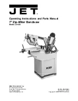
Страница 28: ...28 Wiring Diagram WMH Tool Group Inc 427 New Sanford Road LaVergne Tennessee 30786 Phone 800 274 6848 www wmhtoolgroup com...

Отзывы: