background image

4

Electrical Requirements

In the event of a malfunction or breakdown, grounding provides a path of least resistance for electric
current to reduce the risk of electric shock. This tool is equipped with an electric cord having an
equipment-grounding conductor and a grounding plug. The plug must be plugged into a matching outlet
that is properly installed and grounded in accordance with all local codes and ordinances.

Do not modify the plug provided. If it will not fit the outlet, have the proper outlet installed by a qualified
electrician.

Improper connection of the equipment-grounding conductor can result in a risk of electric shock. The
conductor, with insulation having an outer surface that is green with or without yellow stripes, is the
equipment-grounding conductor. If repair or replacement of the electric cord or plug is necessary, do not
connect the equipment-grounding conductor to a live terminal.

Check with a qualified electrician or service personnel if the grounding instructions are not completely
understood, or if in doubt as to whether the tool is properly grounded.

Use only three wire extension cords that have three-prong grounding plugs and three-pole receptacles
that accept the tool’s plug.*

Repair or replace a damaged or worn cord immediately.

This tool is intended for use on a circuit that has an outlet that looks like the one illustrated in Figure A
below. The tool has a grounding plug that looks like the grounding plug as illustrated in Figure A below.
A temporary adapter, which locks like the adapter as illustrated in Figures B below, may be used to
connect this plug to a two-pole receptacle, as shown in Figure B if a properly grounded outlet is not
available.** The temporary adapter should only be used until a properly grounded outlet can be installed
by a qualified electrician. The green colored rigid ear or tab, extending from the adapter, must be
connected to a permanent ground such as a properly grounded outlet box.

* Canadian electrical codes require extension cords to be certified SJT type or better.
** Use of an adapter in Canada is not acceptable.

Содержание AFS-1500

Страница 1: ...OWNER S MANUAL AFS 1500 Air Filtration JET EQUIPMENT TOOLS INC P O BOX 1349 253 351 6000 A WMH Company Auburn WA 98071 1349 Fax 800 274 6840 www jettools com e mail jet jettools com M 708614 6 2001 ...

Страница 2: ... or accidents normal wear and tear repair or alterations outside our facilities or to a lack of maintenance THE JET GROUP LIMITS ALL IMPLIED WARRANTIES TO THE PERIOD SPECIFIED ABOVE FROM THE DATE THE PRODUCT WAS PURCHASED AT RETAIL EXCEPT AS STATED HEREIN ANY IMPLIED WARRANTIES OR MERCHANTIBILITY AND FITNESS ARE EXCLUDED SOME STATES DO NOT ALLOW LIMITATIONS ON HOW LONG THE IMPLIED WARRANTY LASTS S...

Страница 3: ...eep tools sharp and clean for best and safest performance Follow instructions for lubricating and changing accessories 16 DISCONNECT TOOLS before servicing and when filters 17 USE RECOMMENDED ACCESSORIES The use of accessories and attachments not recommended by manufacturer may cause hazards or risk of injury to persons 18 AVOID ACCIDENTAL STARTING Make sure switch is in OFF position before pluggi...

Страница 4: ...an or service personnel if the grounding instructions are not completely understood or if in doubt as to whether the tool is properly grounded Use only three wire extension cords that have three prong grounding plugs and three pole receptacles that accept the tool s plug Repair or replace a damaged or worn cord immediately This tool is intended for use on a circuit that has an outlet that looks li...

Страница 5: ...ug before servicing or changing filters 3 If ceiling mounted bottom of air cleaner must be at least 7 feet above the floor 4 If ceiling mounted mounts must be anchored to building structure which will support a minimum of at least 150 pounds Never mount to surfaces such as dry wall or false ceiling grids etc 5 To reduce the risk of electrical shock do not expose air cleaner to water or rain 6 Neve...

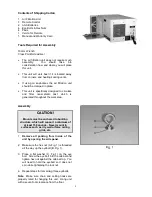
Страница 6: ...metallic dust which is generated throughout the work area Assembly CAUTION Mounts must be anchored to building structure which will support a minimum of at least 150 pounds Never mount to surfaces such as dry wall or false ceiling grids etc 1 Remove all packing from inside of the unit by opening the side panel 2 Make sure the hex nut A Fig 1 is threaded all the way up the eyebolt B Fig 1 3 Place a...

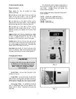
Страница 7: ...Overload reset switch F Fig 2 will pop in the case of overload Wait 3 5 minutes and press the reset switch back in to the normal position Changing the Filters WARNING To reduce the risk of injury disconnect the air filtration unit from the power source unplug before servicing or changing filters Failure to comply may cause serious injury Outer Filter remove from the side of the cabinet A Fig 3 Inn...

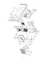
Страница 8: ...8 Parts Breakdown ...

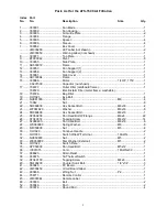
Страница 9: ... OO1023 Eye Bolt 4 20 NH061000 Nut M6 4 21 10042 Nut 6 22 SR060600 Hex Socket Bolt M6x30 4 23 WF061620 Washer M6x16 8 24 SR089400 Hex Socket Bolt M8x16 1 25 SF069200 Pan Head Bolt W Flange M6x8 22 26 ST049314 Tapping Screw M4x12 14 27 SJ089400 Pan Head Bolt M8x16 6 28 WS080000 Spring Washer M8 6 29 NF050800 Nut M5 4 30 OO1029 Concave Handle 2 31 OO1033 Switch Wire W Terminal 18AWG 1 32 NH050800 Nu...

Страница 10: ...10 Optional Replacement Filters 708727 Outer Filter cardboard frame 708729 Electrostatic Filter metal frame washable 708726 Inner Filter 708728 Charcoal Filter Wiring Diagram ...

Отзывы: