16
Conveyor Belt Replacement
1. Unplug the machine from the wall
receptacle, and unplug the motor cord from
the control box receptacle.
2. Raise drum to its highest position using the
handwheel.
3. Loosen the conveyor take-up screw nuts
(A, Fig. 20) to relieve belt tension, and slide
the driven roller fully inward.
4. Remove the four bolts that attach the
conveyor table to the base. Lift up the
conveyor table and remove it from machine.
Avoid tearing the belt on any edges
underneath the conveyor bed.
5. Install new belt, and re-install conveyor
table. Take care not to damage the
Trackers. Tension and track the new belt.
Note:
If the conveyor belt continually tracks to
one side of the machine, reversing the belt on
the conveyor bed may remedy the problem. To
make sure the conveyor bed is not twisted,
place a level on the conveyor bed. Level the
machine if needed. If there is still a problem,
proceed with the steps below:
Step 1
: Check the conveyor drive roller and the
driven roller to make sure they are parallel to the
surface of the conveyor bed. To do this, first
center the conveyor belt on the bed. Then lay a
straight-edge on the exposed edge of the
conveyor bed on the left (outboard) side,
extending it over the roller. Note the distance
between the roller and the straightedge.
Step 2:
Now repeat Step 1 on the right (inboard)
side of conveyor. Compare the measurements
from side to side. If they are not equal, loosen
one of the brackets that hold the roller in place.
Tip this bracket until the distance between the
roller and the straight-edge are equal from side
to side, then tighten the bracket.
Checking Drum Alignment
The sanding drum must be aligned parallel to
the conveyor bed for proper machine operation.
The sanding drum comes preset from the
factory. If a problem with the drum alignment
occurs, follow the instructions below.
First inspect the alignment with a gauge of some
kind. The following procedure uses a steel
straight edge as a gauge.
1. Unplug sander from power source.
2. Open the dust cover and remove the
abrasive strip from the drum.
3. Insert gauge between the drum and con-
veyor bed at the outer end of the drum
(Figure 21).
Figure 21
With the dust cover open, lower sanding
drum while slowly rotating drum by hand
until the drum lightly contacts the thickness
gauge.
4. Remove thickness gauge and place under
drum at the other end.
5. If the drum does not contact the thickness
gauge to the same degree as the opposite
end of the drum, alignment is necessary.
To align the drum:
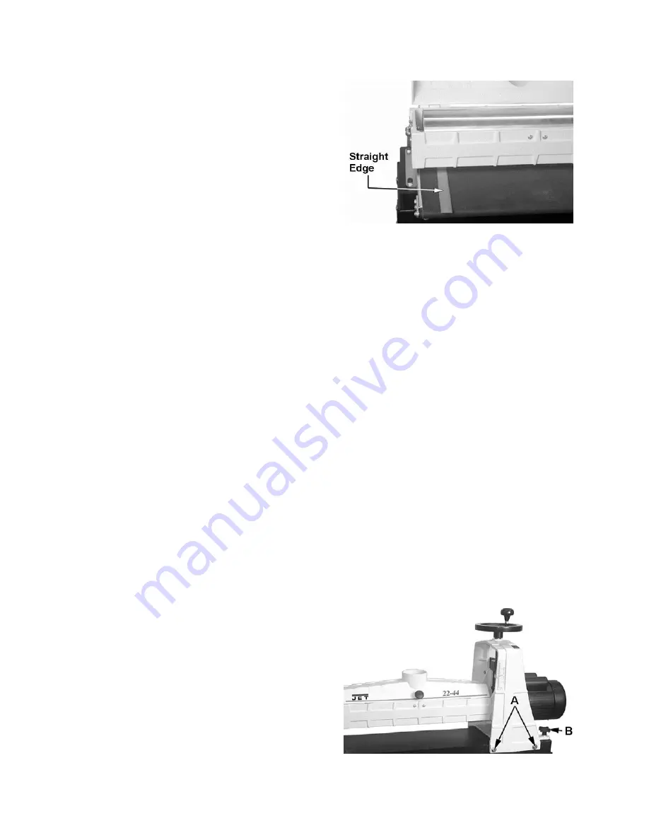
6. Loosen the four 3/8” hex cap screws – two
front, two rear (A, Fig. 22). This allows the
entire drum carriage and shroud to be
pivoted on two screws – one screw in front,
one in back.
7. Lay the thickness gauge under the drum
lengthwise. See Figure 23. Rotate the fine
tune adjustment knob (B, Fig. 22) until the
drum contacts the gauge equally along its
entire surface. Rotate the knob clockwise to
raise the outboard end of the drum,
counterclockwise to lower the outboard end
of the drum. Use the height adjustment
handwheel to raise or lower the entire drum.
8. When drum is parallel to conveyor, tighten
the four screws (A, Fig. 22).
Conveyor table removed for clarity
Figure 22
Содержание 22-44 OSC
Страница 27: ...27 Drum Head Assembly Exploded View...
Страница 30: ...30 Conveyor and Motor Assembly Exploded View...
Страница 35: ...35 Wiring Diagram...
Страница 36: ...36 427 New Sanford Road LaVergne Tennessee 37086 Phone 800 274 6848 www jettools com...


