


4
PHYSICAL ENVIRONMENT AND OPERATING CONDITIONS
The machine is designed for not using at the potentially explosive environment.
Generally, the machine should be installed under the following conditions:
a. The minimum requirement for all electrical equipment is correct operation between
air temperature of +5
℃
and +45
℃
.
b. Electrical equipment is capable of operating correctly when the relative humidity
does not exceeding 50% at a maximum temperature of +45
℃
.
c. Electrical equipment is capable of operating correctly at altitudes up to 1000 m
above mean sea level.
d. Electrical equipment is designed to withstand to protected against the effects of
transportation, and storage temperature within a range of -25
℃
to +55
℃
and for short
periods not exceeding 24h at up to + 70
℃
.
e. Atmosphere: Free from excessive dust, acid fume, corrosive gases and salt.
f. Avoid exposing to direct sunlight or heat rays.
g. Avoid exposing to vibration environmental.
h. Have to connect to the factory grounding system correctly .
i. Away from electric magnetic interference source sites, such welding, discharge
machine.
ELECTRICALLY SUPPLY
The following AC supply information:
a. Voltage Steady state voltage: 0.9 to 1.1 of nominal voltage.
b. Frequency 0.99 to 1.01 of nominal frequency continuously;0.98 to 1.02 short time.
c. Harmonic distortion not exceeding 10 % of the total r.m.s. voltage between live conductors
for the sum of the 2nd through to the 5th harmonic.
d. Voltage interruption Supply interrupted or at zero voltage for not more than 3 ms at any
random time in the supply cycle with more than 1 s between successive interruptions.
e. Voltage dips Voltage dips not exceeding 20 % of the peak voltage of the supply for more
than one cycle with more than 1 s between successive dips.
Содержание PRINCE
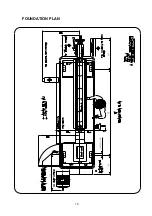
Страница 17: ...16 FOUNDATION PLAN 300 40X4HOLES A 350 500 570 ...
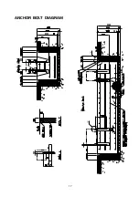
Страница 18: ...17 ANCHOR BOLT DIAGRAM ...
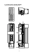
Страница 19: ...18 CONNECTION OF EXTRACTION SYSTEM 18 To Extraction System 18 ...