


26
CHUCK JAW DETAIL
Top jaws should be designed to hold the workpiece
as close to the chuck face as possible. Excessive
jaw height reduces the effective gripping force
available and is detrimental to accuracy. As a
general rule, the height of the grip point above the
chuck face should not exceed one quarter of the
chucks’ diameter.
Large, heavy top jaws should be avoided if
possible since the loss of gripping force due to
centrifugal effects at high spindle speeds is
increased. If heavy jaws are unavoidable, it may be
necessary to restrict the spindle speed below the
chucks’ maximum recommended speed to ensure
that sufficient gripping force is retained to hold the
workpiece.
All top jaws in a set should be of equal weight to
ensure that no out-of-balance forces occur. In the
case of workpieces with a residual out-of-balance,
this may be corrected by designing the top jaws to
counteract the imbalance component. Alternatively,
it may be necessary to restrict the machine to low
speeds to avoid possible vibration problems.
Ideally, top jaws should not extend beyond the
chuck periphery. If this is unavoidable, the amount
of projection should be restricted within safe limits
bearing in mind that the loss in gripping force due
to centrifugal effect is a function of the product of
top jaw mass and the distance to the jaws’ centre
of mass about the chucks’ rotational axis.
Precautions should also be taken to ensure that
projecting top jaws will not collide with tooling
during the machining cycle.
Care should be exercised in machining workpieces
whose length protrudes excessively beyond the
chuck jaws. As a general guide, for workpieces up
to approximately one third of the chuck diameter
whose inner end face is located close to the chuck,
machining should not be carried out at a distance
greater than five times the workpiece diameter or
three times the axial length gripped by the jaws
measured from the outer end of the jaws.
The lesser of these values should be used and the
maximum height of the top jawsshould be
restricted to one quarter of the chuck diameter.
The proportions for this condition are shown below.
When the workpiece diameter is greater than approximately
one third of the chuck diameter and the workpiece is well
supported axially close to its outer periphery, the distance to
the machine point from the outer end face of the jaws
should not normally exceed three quarters of the workpiece
diameter. This is based on the assumption that the axial
length of the workpiece gripped by the jaws is not less than
one tenth of the workpiece diameter.
The proportions for this condition are shown below
.
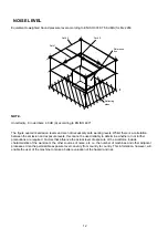
Содержание PRINCE
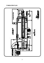
Страница 17: ...16 FOUNDATION PLAN 300 40X4HOLES A 350 500 570 ...
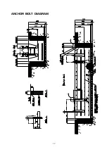
Страница 18: ...17 ANCHOR BOLT DIAGRAM ...
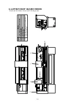
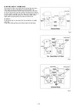
Страница 19: ...18 CONNECTION OF EXTRACTION SYSTEM 18 To Extraction System 18 ...