background image

500 795/Rev D/07-14


Page 4 


Fran

ç

ais


Consignes de s

écurité


Veuillez lire attentivement ces informations avant d'installer ou d'utiliser cet équipement.


1.


L'appareil décrit dans ce manuel est conçu pour n'être utilisé que par 

un 

du personnel qualifié. Tous 

les réglages et toutes les interventions d'entretien  ou de réparation doivent être effectués tel que 
décrits dans ce manuel, par une personne habilitée et ayant été informée des risques encourus.


2.


travail sûres, en complément des instructions détaillées fournies dans ce manuel.


3.


Aucun  élément  autre  que  ceux  définis  dans  les  procédures  d'entretien  indiquées  dans  le  présent 
manuel n'est réparable directement par l'utilisateur. Le retrait des capots et les tentatives de réglage 
ou  d'entretien  du  fait  d'un  membre  du  personnel  non  qualifié  conduiront  à  l'annulation  de  la 
garantie et sont susceptibles d'entraîner des frais supplémentaires en cas de réparation.


4.


Lors  de  l'utilisation  de  produits  chimiques,  une  attention 

particulière  doit  impérativement  être 

portée  aux  fiches  de  données  de  sécurité  qui  les  accompagnent.  Les  procédures  de  laboratoire 


5.


En cas de suspicion d'altération de la sécurité de l'appareil de quelque manière que ce soit, celui

-ci 

doit être  mis hors service et son utilisation doit être rendue impossible. L'anomalie ou panne doit 


REMARQUE :

 le non-

respect des conditions d'utilisation de l'équipement indiquées dans ce manuel du 

fabricant  est susceptible  de  compromettre  votre  sécurité  et  d'entrainer  l'annulation  de  la garantie.  La 
garantie ne couvre pas les dommages causés par une mauvaise ins

tallation ou une mauvaise utilisation 

de l'équipement.


1.1. 


Prévention des incendies et des chocs électriques.


Afin d'éviter tout risque d'incendie ou de choc électrique, 

N'OUVREZ 

PAS

 votre appareil sans autorisation. 

Seul un personnel qualifié est 

habilité à effectuer des interventions de réparation sur l'appareil.  


Ne  remplacez  les  fusibles  qu'avec  les  références  indiquées  dans  le 

chapitre 4.1.2. 


Assurez-

vous que l'alimentation secteur soit conforme aux données 

nominales mentionnées sur la plaque signalétique située à l'arrière 

de cet appareil. 


N'utilisez 

jamais


cet  appareil  sans  prise  électrique


raccordée  à  la 

terre ou  à une  masse.  Assurez

-vous  que  l'alimentation  secteur  soit 

correctement  reliée  à  la  terre  ou  à  une  masse  conformément  aux 
réglementations locales en vigueur. 


DOMINIQUE DUTSCHER SAS

Содержание PFP7

Страница 1: ...500 795 Rev D 07 14 Flame Photometer Models PFP7 and PFP7 C Operating Manual D O M I N I Q U E D U T S C H E R S A S...

Страница 2: ...ny intended operation The fault condition should immediately be reported to the appropriate servicing authority NOTE your basic safety protection afforded by the equipment and may invalidate the warra...

Страница 3: ...lator conforms to the applicable national requirements Take care when fitting and removing the capillary tube to the nebulizer needle It is not recommended to leave the flame photometer unattended dur...

Страница 4: ...he manufacturer responsible bodies should check with the manufacturer that the proposed method will not damage the equipment In order to completely disconnect power to the flame photometer the mains p...

Страница 5: ...de laboratoire 5 En cas de suspicion d alt ration de la s curit de l appareil de quelque mani re que ce soit celui ci doit tre mis hors service et son utilisation doit tre rendue impossible L anomalie...

Страница 6: ...un d gagement d au moins 1m au dessus de la chemin e Assurez vous que la chemin e ext rieure soit correctement install e avant d utiliser l quipement Attention assurez vous que les tuyaux de gaz et d...

Страница 7: ...vertissement un r glage inappropri du robinet de combustible permettant un d bit excessif entrainera une flamme trop importante vitez d installer le photom tre de flamme dans une zone expos e aux cour...

Страница 8: ...zzati Implementare le procedure di laboratorio comunemente accettate per la manipolazione sicura dei prodotti chimici 5 Se si sospetta che la sicurezza dell unit sia stata compromessa disattivare e re...

Страница 9: ...sopra la ciminiera Assicurarsi che la ciminiera esterna sia stata adeguatamente installata prima di utilizzare l apparecchiatura Attenzione Prima dell accensione assicurarsi che i tubi del gas e dell...

Страница 10: ...sovraregolazione della valvola del carburante genera una fiamma eccessiva Non installare il fotometro a fiamma in zone soggette a correnti ma assicurarsi che vi sia una ventilazione adeguata per evit...

Страница 11: ...ceptados para la manipulaci n segura de los productos qu micos 5 Si se sospecha que la seguridad de la unidad ha sido alterada de alguna forma la unidad debe inutilizarse y deben tomarse medidas para...

Страница 12: ...y al menos 1 m de espacio libre por encima de la chimenea Aseg rese de que la chimenea externa est instalada apropiadamente antes de poner en funcionamiento el equipo Atenci n Aseg rese de que las tub...

Страница 13: ...e excesivo de la v lvula de combustible provocar una llama excesiva Evite instalar el fot metro de llama en zonas expuestas a corrientes de aire pero aseg rese de que haya una ventilaci n adecuada par...

Страница 14: ...Es sind allgemein anerkannte Laborverfahren f r die sichere Handhabung von Chemikalien einzusetzen 5 Falls vermutet wird dass die Sicherheit des Ger ts auf irgendeine Weise beeintr chtigt wurde ist d...

Страница 15: ...n jede Richtung befindet und mindestens 1 m Platz oberhalb des Schornsteins vorhanden ist Stellen Sie sicher dass der u ere Schornstein vor dem Betrieb des Ger ts ordnungsgem installiert wurde Achtung...

Страница 16: ...lammenphotometer Achtung Eine berm ige Justierung des Brennstoffventils f hrt zu berm iger Flammenbildung Stellen Sie das Flammenphotometer nicht in zugigen Bereichen auf aber sorgen Sie daf r dass ei...

Страница 17: ...lysis Preparation 28 3 1 Calibration standards 28 3 2 Sample preparation 30 3 3 Dilution 31 SECTION 4 32 Operation 32 4 1 Front and rear panel controls 32 4 2 Operation Flame Ignition and Optimisation...

Страница 18: ...e results 44 7 3 Unable to set standard reading 44 7 4 Non linear results 45 7 5 Flame will not light 45 7 6 No electrical power 45 7 7 Unable to set blank 46 7 8 No reading on display 46 SECTION 8 46...

Страница 19: ...ed 0 10 0 mmol L K Limits of Detection Na 0 2ppm Na 0 2ppm K 0 2ppm K 0 2ppm Li 0 25ppm Li 0 25ppm Ca 15ppm Ba 30ppm Reproducibility 1 Coefficient of variation C V for 20 consecutive samples using 10p...

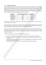
Страница 20: ...oncentration the intensity of the emission is directly proportional to the number of atoms returning to the ground state This is in turn proportional to the absolute quantity of the species volatized...

Страница 21: ...avelengths are easily isolated from those of most other elements due to wide spectral separation The analysis of Na K Li Ba and Ca are typically determined at low temperatures i e 1500 2000 C therefor...

Страница 22: ...ing standards The performance of the instrument depends upon the accuracy and purity of the calibration standards 4 If standard solutions are required to be stored for any length of time or at an elev...

Страница 23: ...2 L P G regulated to 10 15 inches water gauge 0 36 0 54psi or 0 025 0 038kg cm2 Suitable regulators are available from Jenway refer to Section 2 5 2 1 3 Air A supply of dry clean and pulse free air at...

Страница 24: ...onal as ordered 013 046 Nebuliser inlet tube 500mm 500 193 Gas tube low pressure 2 metres 500 191 Silicon rubber tube drain 023 003 Air tube 2 metres 500 192 Nozzle 1 gas 026 012 Nozzle 2 air 026 013...

Страница 25: ...he restrictor screw 5 fitted into the end of the fuel inlet 6 on the mixing chamber The restrictor screw should remain in place if butane propane or L P G is to be used as fuel Keep the restrictor scr...

Страница 26: ...Fuel to mixing chamber inlet 7 Mixing chamber to drain outlet 8 End cap 9 Drain trap clip 10 Drain trap to waste containter tubing 11 Mixing chamber to drain trap tubing 12 Compressed air to nebuliser...

Страница 27: ...tor 2 Plug the power cable into the POWER IN socket 17 figure 2 3 2 If necessary connect a suitable plug to the 3 pin AC supply lead The colours of the wires conform to the internationally recognised...

Страница 28: ...or variations in specification that could degrade the performance of the instrument Accessories Part Code Model 8515 air compressor 220V 50Hz 535 001 Model 8516 air compressor 110V 60Hz 535 002 Butane...

Страница 29: ...2 Always ensure that the standards encompass the expected range of the sample concentrations 3 Standards should be prepared so as to ensure that the region in which measurements are made coincide wit...

Страница 30: ...olution for use with the flame photometer this stock solution should be diluted 1 in 50 Calculation Atomic weight K 39 1 Molecular weight KCl 74 56 Therefore 0 477g KCl contains 0 477 x 39 1 0 25g K 7...

Страница 31: ...oration of the solvent that could lead to elevated concentrations 6 When in doubt about the equipment or application the operator should contact Jenway at jenwayhelp bibby scientific com for advice 3...

Страница 32: ...us levels of dilution will often be necessary Good quality deionised water should normally be used for carrying out these dilutions and it is recommended that the same batch of water should be used fo...

Страница 33: ...led by the front panel power switch 2 Ignition A spring loaded switch which when depressed will cause an electrical discharge between the ignition electrode and the burner unit thereby causing fuel ig...

Страница 34: ...itions 3 and 4 will normally be blank 4 1 2 Rear panel controls Figure 4 1 2 1 Rear panel 1 VOLTAGE SELECTION A two position switch marked 230 and 115 These positions allow operation from the voltage...

Страница 35: ...or 0 025 0 38kg cm2 See section 2 1 2 for information on different fuel types 7 AIR 5 16 connector for air tubing IMPORTANT Air pressure on the inlet to the instrument must not exceed 30psi 2kg cm2 Se...

Страница 36: ...irate a standard solution of slightly higher concentration than expected in samples to be tested Adjust the fine and coarse control until a positive reading obtained This is a nominal value to be used...

Страница 37: ...o that they lie on the linear part of the curve The user can manually construct a calibration curve using standard solutions containing known concentrations of the elements to be determined and if nec...

Страница 38: ...ck the blank setting and adjust Aspirate the remaining standard solutions if used to construct the calibration curve note the When the blank and standards are set unknown samples can be aspirated and...

Страница 39: ...least 1 in 100 and set the display reading accordingly using the fine coarse sensitivity 4 Adjust the fuel valve in a clockwise direction until a peak reading is obtained Re set display reading accord...

Страница 40: ...me is alight 4 The top of the instrument chimney unit becomes very hot when running and can cause severe burns if touched 5 The exhaust gases from the flame are very hot and the area approximately 1 m...

Страница 41: ...6 Finger operated plungers for easy draining 5 1 2 Specifications Model Large Small Part code 500 177 500 176 Port size Maximum operating pressure 100psi 100psi Working temperature range 5 to 80 C wit...

Страница 42: ...ply to the flame photometer is switched on 2 Connect the air tubing supplied with the flame photometer to the compressor outlet nozzle and secure with a hose clip 3 Connect the other end of the air tu...

Страница 43: ...r one minute 3 The consumption rate should be between 2 and 6ml min If correct no further action is required 4 If the consumption rate is too low this is likely to be caused by a blockage in the fine...

Страница 44: ...llow 30 minutes for the burner system to cool down 3 Disconnect the mixing chamber from the chimney unit by unscrewing the knurled locking ring and dropping the chamber clear of the chimney 4 Remove t...

Страница 45: ...n 4 2 Operation Fuel cylinder nearly empty Replace cylinder with a fully charged one Instrument in strong draught Relocate the instrument Instrument in very bright sunlight Relocate the instrument Ins...

Страница 46: ...e temperature not correctly set Ensure the fuel valve is correctly set for the element being determined refer to Section 4 2 Instrument not draining adequately the drain trap is at the correct level 7...

Страница 47: ...1 Minor Spares Kit PFP7 MINKIT Description Part code Quantity Nebuliser I 500019 1 Cleaning Wire 3x150mm I 500194 1 Cleaning Solution 025016 2 Ignition Probe Assembly PFP7 IPA 1 Mk2 Small Knob Blank...

Страница 48: ...500 795 Rev D 07 14 Page 47 D O M I N I Q U E D U T S C H E R S A S...

Страница 49: ...500 795 Rev D 07 14 Page 48 D O M I N I Q U E D U T S C H E R S A S...

Страница 50: ...33 1 64 45 13 00 Fax 44 0 1785 810405 e mail info bibby scientific com e mail bsf bibby scientific fr e mail bibby bibby scientificasia com www bibby scientific com www bibby scientific com www bibby...

Отзывы: