JWM990
4
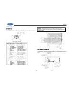
WIRING
The wiring diagram depicts all the wiring connections required for proper operation of the unit.
SHOWN FROM PIN VIEW
PIN NO.
WIRE COLOR
DESCRIPTION
1
PINK/BLACK
RIGHT (C) SPEAKER (-)
2
PINK
RIGHT (C) SPEAKER (+)
3
LIGHT GREEN
LEFT (C) SPEAKER (+)
4
LIGHT GREEN/BLACK
LEFT (C) SPEAKER (-)
5
BROWN/BLACK
LEFT (B) SPEAKER (-)
6
GRAY
FRONT RIGHT (A) SPEAKER (+)
7
GRAY/BLACK
FRONT RIGHT (A) SPEAKER (-)
8
N/A
N/A
9
WHITE/BLACK
FRONT LEFT (A) SPEAKER (-)
10
WHITE
FRONT LEFT (A) SPEAKER (+)
11
ORANGE
RIGHT (B) SPEAKER (+)
12
ORANGE/BLACK
RIGHT (B) SPEAKER (-)
13
BROWN
LEFT (B) SPEAKER (+)
14
BLUE
AMP REMOTE (+12VDC 100mA)
15
RED
+12VDC SWITCHED
16
BLACK
GROUND
17
VIOLET
RIGHT REAR (A) SPEAKER (+)
18
VIOLET/BLACK
RIGHT REAR (A) SPEAKER (-)
19
GREEN/BLACK
LEFT REAR (A) SPEAKER (-)
20
GREEN
LEFT REAR (A) SPEAKER (+)
CONNECTIONS
The diagram below depicts all the available audio/video connections available to use with your
system.
WARNING
: Wiring harness comes with stripped and tinned leads to aid in the
installation process. Any unused speaker wires
must
have their exposed ends cut off or
insulated individually.


