6
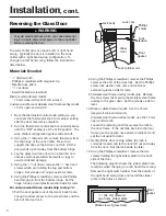
13. Relocate the light striker plate to the opposite end of
the door, lining up the two holes in the striker plate,
with the two holes at the opposite center of the
door. Remove the two hole plugs (select models)
and resecure the striker plate with the two screws.
For custom wood frame model, skip to step 21.
14. Lift the door or stainless steel frame overlay end
up, opposite of where the door lock was previously
located and insert the lock from the front side.
Hold the lock in place and gently lower the door or
stainless steel frame overlay back down.
Black or white framed model:
Use the 15 mm
deep-well socket and wrench.
Stainless steel frame overlay:
15 mm open-end
wrench.
Reassemble the door lock’s retaining nut to the
lock. Follow step 15 before tightening the door
lock’s nut.
15. Reassemble the Phillips screw, lock washer and
lock cam back into the lock in the order they were
removed. Position the door lock’s cam so that it
projects upward from the top of the door. Make
sure the key slot on the front is aligned vertically,
from top to bottom. Lightly tighten the Phillips
screw to secure the lock assembly. Now tighten
the door lock’s retaining nut.
Stainless steel frame overlay model:
Now tighten
the retaining nut.
Black or white framed model:
Mark the alignment
of the door lock and then remove the Phillip’s
screw and lock cam. Now tighten the retaining
nut, then reassemble the lock cam and Phillip’s
screw.
Steps 16 – 19 are needed for stainless steel frame
overlay model only. If reversing the door on a
black or white framed model, skip to step 20.
16. Using the Phillips head screwdriver, remove the
door lock’s Phillips screw at the end of the door
lock’s extension and remove the lock cam. Set the
lock cam aside for reassembly later. Resecure the
lock extension to the lock with the Phillips screw.
17. Lay the stainless steel frame overlay face down on
a smooth surface. Align the glass door directly
over the stainless steel frame overlay so that the
lock extension will go through the hole in the glass
door that is on the opposite end of where the lock
was originally located. Look for the mounting
holes in the glass door and align these holes with
the threaded weld nuts in the overlay. Use the ten
screws removed in step 9 to resecure the stainless
steel frame overlay to the glass door.
18. Remove the door lock’s Phillips screw and reassemble
the lock cam to the lock extension and resecure.
19. Check to see that the lock easily turns a quarter
turn from vertical to horizontal.
20. Reinstall the door gasket by pressing it back into
the door channel. Make certain the door gasket is
secure and sealed. If necessary, use the small flat-
blade screwdriver to help push the arrowhead,
section of the door gasket into the gasket channel.
21. Locate the two hinges that were removed from the
right-hand side of the wine chiller. Insert the hinge
pin screw into the hinge that was on top and
tighten securely. This hinge will be the bottom
hinge on the left side of the cabinet.
22. Remove the six plastic hole plugs from the left
hand side hinge mounting holes.
23. Using the
5
⁄
16
" nut driver, mount the hinges on the
left side of the wine chiller using the six set-aside
5
⁄
16
" hex screws. Tighten screws securely.
24. Install custom wood frame panel (select models,
refer to page 7).
25. Gently lift the door up and place the door on the
bottom hinge/hinge pin assembly. Make sure the
plastic washer is installed on the bottom hinge
before placing the door on it.
26. Using the
1
⁄
8
" Allen wrench, secure the door to the
top hinge with the Allen hinge pin screw.
27. Make certain that the door swings freely, the door
gasket seals properly and the interior light goes on
and off as the door opens and closes.
28. Confirm that door lock turns a quarter turn from
vertical to horizontal and that this locks the door
closed.
29. Replace all hole plugs.
30. Reconnect the power to the wine chiller. Return
the control knob to its previous setting.
Содержание JUC2450ACX
Страница 21: ...2003 Maytag Appliances Company 16022323 Rev 0 A 1 Appendix A...
Страница 38: ...16 Notes...
Страница 40: ...2003 Maytag Appliances Company 16022323 Rev 0 B 1 Appendix B...


