


14
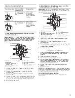
4.
Drill 4 holes aligned through the motor housing mounting
brackets (2 holes each bracket) to the cabinet floor. Using
4 screws (not supplied), secure the motor assembly to the
cabinet floor.
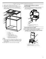
5.
Assemble ducting from blower motor assembly venting
outlet to the exterior 3
Z\v
" x 10" (8.3 cm x 25.4 cm) exhaust
ducting. (See “Cabinet Cutout for Vented Installations”
for recommended cutout area locations for exterior
exhaust ducting).
6.
Use metal duct tape to secure and seal all duct joints.
Style 2 – Recirculation Cabinet Front Kick Plate
Installations
(Use “Style 2 – Cabinet Cutouts for Recirculation Front
Kick Plate Installations” in the “Cutout Dimensions” section
for recirculation out of the front kick plate of the cabinet.)
NOTE:
Recirculation Kit required. See the “Accessories”
section in your Use and Care manual to order.
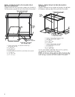
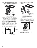
IMPORTANT:
The sub-floor under the cabinet must be the
same surface height as the cabinet bottom. An additional
piece of sub-flooring may be needed.
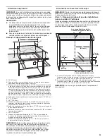
A
B
A. Cabinet floor
B. Wood screws M6 x 16 mm (4)
Floor
Bottom of Cabinet
Sub-floor
under cabinet
Sub-floor
under cabinet
Bottom of cabinet
Floor
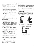
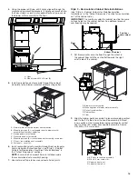
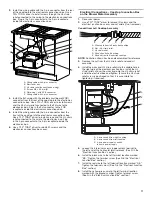
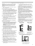
1.
Set blower motor onto the floor through the cutout in
the cabinet floor with the vent outlet toward the front
of the cabinet.
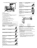
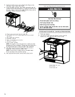
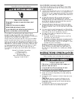
2.
Align the blower motor assembly 2-piece telescoping vertical
duct to the 90° elbow from the cooktop assembly. Extend
inner section of the 2-piece telescoping rectangular vertical
duct to fit over the 90° elbow from the cooktop assembly.
Secure with M4 x 9.5 mm screws.
3.
Tighten all of the screws connecting the ducting and use
metal duct tape to seal all duct joints.
A
C
B
E
D
A. Blower motor assembly
B. Mounting tabs of blower motor assembly
C. Cutout in cabinet floor
D. Cabinet floor
E. Floor
C
A
B
D
B
A. 90° duct to cooktop assembly
B. M4 x 9.5 mm screws (4)
C. Upper vertical duct
D. Lower vertical duct


