


Testing Procedures
!
WARNING
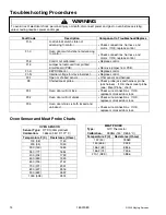
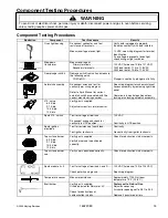
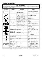
To avoid risk of electrical shock, personal injury or death; disconnect power and gas to oven before servicing,
unless testing requires power and/or gas.
16 16022089
©2005 Maytag Services
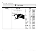
Illustration Component
Test
Procedure
Results
Bake burner
Verify gas is supplied.
Orifice adjusted for Natural or LP ...........
Check for obstructions or
contamination in ports ............................
Factory set to Natural Gas.
Adjust as necessary.
Air shutter opening set to .469 to .531.
Replace if punctured or torn.
Ignitor
Test for voltage at terminals ...................
Test for the amount of amperage in
the circuit................................................
(Ignitor may glow but not have
sufficient amperage to open valve.)
120 VAC.
3.2
−
3.6 Amps If not replace.
Broil element
Disconnect wiring to element and
measure resistance of terminals.............
Measure voltage at broil element............
Approximately 16
Ω
.
120 VAC.
Hi-limit temperature
switch
Normally closed, verify operation:
Open: 269° to 291°F (132° to 144°C) .....
Closed: 173° to 207°F (78° to 97°C).......
Infinite.
Continuity.
Double thermal valve/
shut off valve
Verify gas supply is turned on at
regulator .................................................
Attached to pressure regulator at the
rear of the unit.
Gas ON red tab up (at regulator).
Gas OFF red tab down (at regulator).
Pressure regulator
Verify gas pressure (W.C.P.)..................
If on LP service verify proper gas
supply conversion.
5
"
Natural
10
"
LP/propane
Gas ON red tab up.
Gas OFF red tab down.
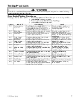
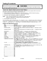
Convection assembly
Convection motor
Model JGS8850AD*
Measure voltage.....................................
Check motor windings to ground ............
120 VAC. (tolerance: 105 to 135 VAC)
No continuity.
RPM: Approx. 800 (tolerance: 600 to
1000 RMP).
Cooling fan motor
Measure voltage.....................................
Check motor windings to ground ............
120 VAC.
No continuity.
RPM: Idle: 3395.
Load:
3000.
Breakdown:
2400.
Venturi, right front, left
front, left rear burners
Shutter settings ...................................... Nominal: .038" (tolerance: .035" to
.041").
Venturi, right rear
burner
Shutter settings ...................................... Nominal: .038" (tolerance: .035" to
.041").
Electronic control
NOTE: To avoid
equipment damage,
use caution when
checking electronic
control circuitry
voltages.
L1 ...........................................................
Jumper ...................................................
Door logic sensor ...................................
Meat probe .............................................
Bake burner............................................
Broil burner.............................................
P26 (Black) to P5 (White): 120 VAC.
P18 to P23 (Black).
P4 (Red, pin 5) to P4 (Black, pin 2):
Door
Locked:
Continuity.
Door
Unlocked:
Infinity.
P2 (Red) to P2 (Red). See
"
Meat
Probe
"
chart.
P17 (Red) to P5 (White): 120 VAC.
P25 (Yellow) to P5 (White): 120 VAC.
Power cord 3-wire
Verify resistance of wires to terminals .... Continuity
Содержание JGS8750ADB
Страница 27: ... 2005 Maytag Services 16022089 A 1 Appendix A ...
Страница 33: ... 2005 Maytag Services 16022089 B 1 Appendix B ...
Страница 34: ...B 2 16022089 2005 Maytag Services Use Information ...
Страница 35: ... 2005 Maytag Services 16022089 B 3 Use Information ...
Страница 36: ...B 4 16022089 2005 Maytag Services Use Information ...
Страница 37: ... 2005 Maytag Services 16022089 B 5 Use Information ...
Страница 38: ...B 6 16022089 2005 Maytag Services Care Information ...
Страница 39: ... 2005 Maytag Services 16022089 B 7 Care Information ...
Страница 40: ...B 8 16022089 2005 Maytag Services Care Information ...
Страница 41: ... 2005 Maytag Services 16022089 C 1 Appendix C ...