


OPERATION
Jenn-Air Built-in Coffee System
n
2-5
7
3.
Press the up and down arrow keys to see:
■
Total cups of coffee made
■
Total liters of water used
■
Total number of descalings
■
Total cups of cappuccinos made
4.
Press MENU once to exit the Statistics menu. Press MENU
again to exit the main menu.
Default Values
This function will restore all settings to the factory-set defaults.
1.
Press MENU.
2.
Press the up and down arrow keys until “DEFAULT VALUES”
is displayed. Press OK.
3.
“OK to confirm” will be displayed. Press OK.
4.
“Restore” will be displayed for a few seconds. All settings will
be reset to default.
5.
Press MENU to exit the menu.
Water Hardness
It is important to set the correct water hardness for proper
descaling.
1.
Remove the “Total hardness test” water hardness strip (found
in the bag containing literature) from its packaging.
2.
Immerse the strip fully in a cup of water for a few seconds.
3.
Remove the strip and wait approximately 30 seconds until it
changes color and red squares appear on the strip.
4.
Press MENU.
5.
Press the up and down arrow keys until “WATER
HARDNESS” is displayed. Press OK.
6.
Press the up and down arrow keys to select the number of
dots corresponding to the number of red squares that have
formed on the test strip. For example, if the test strip shows
3 red squares, select
.
7.
Press OK.
Auto-Off
The coffee system is factory-set to go into standby mode
automatically after 30 minutes of inactivity.
1.
Press MENU.
2.
Press the up and down arrow keys until “AUTO-OFF” is
displayed. Press OK.
3.
Press the up and down arrow keys until the desired period of
time before the coffee system goes into standby mode is
selected: 30 minutes, 1 hour or 2 hours.
4.
Press OK.
5.
Press MENU to exit the menu.
Coffee Temperature
The temperature of the brewed coffee can be changed.
1.
Press MENU.
2.
Press the up and down arrow keys until “COFFEE
TEMPERATURE” is displayed. Press OK.
3.
Press the up and down arrow keys until the desired coffee
temperature is selected: low, medium or high.
4.
Press OK to confirm the temperature chosen.
5.
Press MENU to exit the menu
Descaling
If “DESCALE!” is displayed, the coffee system needs to be
descaled.
NOTE:
Failure to descale the machine regularly can result in
decreased product performance and may result in product
damage.
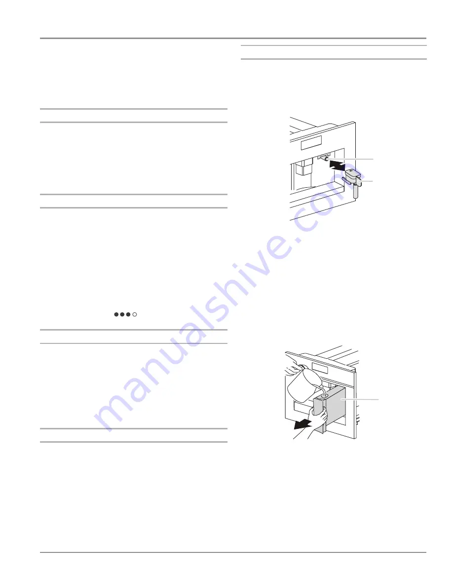
1.
When the machine is ready for use, attach the hot water
spout to the hot water and steam nozzle.
2.
Press MENU.
3.
Press the up and down arrow keys until “DESCALING” is
displayed. Press OK.
4.
“DESCALING OK to confirm” will be displayed. Press OK.
5.
“Add Descaler Press OK” will be displayed. Remove the
water tank and empty the contents. In the water tank, pour in
the contents of a packaged descaler and water, following the
manufacturer’s instructions.
IMPORTANT:
Do not use vinegar to descale the coffee
system. Use a packaged descaling agent. When using a
descaling agent, follow the directions on the package for the
recommended amounts of descaling agent and water.
Replace the water tank.
6.
Place a 2 qt (2 L) or larger container underneath the hot water
spout.
7.
Press OK. “DESCALING UNDERWAY” will be displayed and
the descaling solution will be dispensed.
8.
The descaling program will automatically alternate between
runoffs and pauses.
9.
“RINSING FILL TANK!” will be displayed. Empty the descaling
runoff and replace the container.
10.
Remove the water tank and empty the contents. Rinse the
water tank thoroughly to remove all traces of descaler. Add
3 cups (710 mL) water to the water tank.
11.
Replace the water tank. “RINSING Press OK” will be
displayed. Press OK.
A. Hot water and steam nozzle
B. Hot water spout
A. Water tank
A
B
A
Содержание JBC7624BS
Страница 1: ...JC 01 TECHNICAL EDUCATION Built in Coffee System JOB AID W10647095 JBC7624BS...
Страница 10: ...1 6 n Jenn Air Built in Coffee System GENERAL INFORMATION Notes...
Страница 26: ...2 16 n Jenn Air Built in Coffee System OPERATION Notes...
Страница 39: ...COMPONENT ACCESS Jenn Air Built in Coffee System n 4 7 Jenn Air Built in Coffee System Disassembly Section...
Страница 76: ...Jenn Air Built in Coffee System W10647095...


