Jenn-Air 30

7

Countertop Cutout Dimensions Chart

Electrical Requirements

Observe all governing codes and ordinances. 

Ensure that the electrical installation is adequate and in 
conformance with National Electrical Code, ANSI/NFPA 70 (latest 
edition), or CSA Standards C22.1-94, Canadian Electrical Code, 
Part 1 and C22.2 No. 0-M91 (latest edition) and all local codes 
and ordinances.

If codes permit and a separate ground wire is used, it is 
recommended that a qualified electrician determine that the 
ground path is adequate.

A copy of the above code standards can be obtained from:

National Fire Protection Association
1 Batterymarch Park
Quincy, MA 02169-7471
CSA International
8501 East Pleasant Valley Road
Cleveland, OH 44131-5575

A 120 volt, 60 Hz., AC only, 15-amp, fused electrical circuit is 
required.

If the house has aluminum wiring, follow the procedure 
below:

1. Connect a section of solid copper wire to the pigtail 

leads.

2. Connect the aluminum wiring to the added section of 

copper wire using special connectors and/or tools 
designed and UL listed for joining copper to aluminum.

Follow the electrical connector manufacturer's recommended 
procedure. Aluminum/copper connection must conform with 
local codes and industry accepted wiring practices.

Wire sizes and connections must conform with the rating of 
the appliance as specified on the model/serial rating plate. 
The model/serial plate is located on the front of the downdraft 
vent, above the wiring box cover.

Wire sizes must conform to the requirements of the National 
Electrical Code, ANSI/NFPA 70 (latest edition), or CSA 
Standards C22. 1-94, Canadian Electrical Code, Part 1 and 
C22.2 No. 0-M91 (latest edition) and all local codes and 
ordinances.

Venting Requirements

IMPORTANT: Make sure there is proper clearance within the wall 
or floor before making exhaust vent cutouts.

Use heavy (rigid) metal vent.

Venting system must terminate to the outside.

Do not terminate the vent system in an attic or other enclosed 
area.

Do not use 4" (10.2 cm) laundry-type wall caps.

Do not install 2 elbows together.

Do not use plastic or metal foil vent.

The length of vent system and number of elbows should be 
kept to a minimum to provide efficient performance.

Use no more than three 90° elbows 

Make sure there is a minimum of 24" (61 cm) of straight vent 
between the elbows if more than one elbow is used.

Use clamps or duct tape to seal all joints in the vent system.

Use caulking tape to seal the exterior wall or floor opening 
around cap.

Do not cut joist or stud. If vent cutout falls over a joist or stud, 
a supporting frame must be constructed.

Flexible metal vent is not recommended. If it is used, calculate 
each foot of flexible vent as 2 ft (0.6 m) of rigid metal vent.

Flexible elbows count twice as much as standard elbows.

Recommended vent system length: 

For either interior-mounted or exterior-mounted blower 
installations, the vent system length should not exceed the 
maximum lengths listed in the Maximum Length of Vent System 
chart. See “Calculating Vent System Length” in the “Venting 
Methods” section in the Installation Instructions.

Cold Weather Installations

An additional back draft damper should be installed to minimize 
backward cold air flow and a thermal break should be installed to 
minimize conduction of outside temperatures as part of the vent 
system. The damper should be on the cold air side of the thermal 
break.

The break should be as close as possible to where the vent 
system enters the heated portion of the house.

Makeup Air

Local building codes may require the use of makeup air systems 
when using ventilation systems greater than specified CFM of air 
movement. The specified CFM varies from locale to locale. 
Consult your HVAC professional for specific requirements in your 
area.

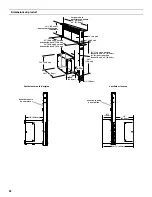
A. ½" (12.7 mm) minimum to 

backsplash or rear wall

B.

³⁄₄

" (19.1 mm) maximum 

backsplash depth

C. 27

¹⁄₂

" (69.9 cm) on 30" (76.2 cm) 

models
33

¹⁄₂

" (85.9 cm) on 36" (91.4 cm) 

models

D. D = Measurement of cooktop rear 

ov 1

¹³⁄₁₆

" (46.2 mm)

A

B

C

D

Содержание 30" RETRACTABLE DOWNDRAFT VENT SYSTEM

Страница 1: ...800 536 6247 or visit our website at www jennair com In Canada call 1 800 807 6777 or visit our website at www jennair ca Instructionsd installationetGuided utilisationetd entretien Au Canada pour ass...

Страница 2: ...ccordements lectriques 30 Contr le du fonctionnement 31 UTILISATION DU SYST ME D EXTRACTION 31 Utilisation du syst me d extraction par le bas 31 ENTRETIEN DU SYST ME D VACUATION 32 Surface du syst me...

Страница 3: ...ardous or explosive materials and vapors CAUTION To reduce risk of fire and to properly exhaust air be sure to duct air outside do not vent exhaust air into spaces within walls or ceilings attics or i...

Страница 4: ...doors and strong heating vents or fans Cabinet opening dimensions that are shown must be used Given dimensions provide minimum clearance Consult the cooktop manufacturer installation instructions befo...

Страница 5: ...m for 30 76 2 cm vent 33 83 8 cm for 36 91 4 cm vent 16 42 0 cm 10 25 4 cm 2 5 4 cm 28 72 4 cm 0 95 cm 1 3 8 cm 13 33 4 cm 5 13 3 cm for 30 76 2 cm vent 8 21 0 cm for 36 91 4 cm vent 1 9 cm As Receive...

Страница 6: ...ng Countertop Cutout Dimensions Chart To avoid mistakes it is recommended that the cooktop and vent cutouts be drawn on the countertop before making any cutouts See the Installation Instructions that...

Страница 7: ...ate to the outside Do not terminate the vent system in an attic or other enclosed area Do not use 4 10 2 cm laundry type wall caps Do not install 2 elbows together Do not use plastic or metal foil ven...

Страница 8: ...x 25 4 cm rectangular vent is required from the blower motor box It can be transitioned to 6 15 2 cm round vent if needed Maximum Length of Vent System Front Standard Mounted Blower Motor Rear Mounted...

Страница 9: ...0 ft 1 5 m 3 x 10 8 3 cm x 25 4 cm flat elbow 12 0 ft 3 7 m 3 x 10 8 3 cm x 25 4 cm wall cap 0 0 ft 0 0 m Vent Piece 6 15 2 cm Round 45 elbow 2 5 ft 0 8 m 90 elbow 5 0 ft 1 5 m 6 15 2 cm wall cap 0 0...

Страница 10: ...stem on its back 2 Remove the 4 screws from the cover plate mounted to the face of the motor box and set them aside 3 Slide the cover plate up and slip it over the keyhole slot shoulder screws Set the...

Страница 11: ...e wire assembly through the opening to the opposite side of the vent box 9 Reassemble the wire assembly and grommet to the wire mounting plate 10 Install the wire mounting plate to the vent box using...

Страница 12: ...ed or CSA approved conduit connector 4 Using 2 or more people insert the downdraft vent into the countertop cutout Position downdraft vent so it is centered in the cutout with the rear flange over the...

Страница 13: ...eration and speed of the blower 3 If the blower does not operate Check that filter or filters are pressed in as far as they will go Check that the circuit breaker has not tripped or a household fuse b...

Страница 14: ...downdraft vent while it is operating 2 Immediately turn off the downdraft vent at the speed control located on the right hand side of the downdraft vent 3 Turn off the power supply to the downdraft v...

Страница 15: ...3 6 1 1 1 1 2 3 4 5 6 7 8 9 10 11 12 1 2 3 Motor Specifications Power supply 120 VAC Frequency 60 Hz Wattage rating 420 W Amperage 3 7 A Motor Resistance BU W 21 6 Ohms BU R 18 Ohms BU GY 14 3 Ohms BU...

Страница 16: ...e address and daytime telephone number 2 Appliance model number and serial number 3 Name and address of your dealer or servicer 4 A clear description of the problem you are having 5 Proof of purchase...

Страница 17: ...e service by an authorized Jenn Air servicer is not available 10 The removal and reinstallation of your major appliance if it is installed in an inaccessible location or is not installed in accordance...

Страница 18: ...18 Notes...

Страница 19: ...n cas de non respect des instructions Votre s curit et celle des autres est tr s importante Nous donnons de nombreux messages de s curit importants dans ce manuel et sur votre appareil m nager Assurez...

Страница 20: ...que d incendie et vacuer ad quatement les gaz veiller acheminer l air aspir par un conduit jusqu l ext rieur ne pas d charger l air aspir dans un espace vide du b timent comme une cavit murale un plaf...

Страница 21: ...r les dimensions indiqu es pour les ouvertures d couper dans les placards Ces dimensions tiennent compte des valeurs minimales des d gagements de s paration Avant d effectuer des d coupes consulter le...

Страница 22: ...76 2 cm 33 83 8 cm pour une vacuation de 36 91 4 cm 16 42 0 cm 10 25 4 cm 2 5 4 cm 28 72 4 cm 0 95 cm 1 3 8 cm 13 33 4 cm 5 13 3 cm pour une vacuation de 30 76 2 cm 8 21 0 cm pour une vacuation de 36...

Страница 23: ...leau des dimensions de l ouverture du plan de travail Pour viter une erreur avant de d couper une ouverture il est recommand de tracer le p rim tre de la table de cuisson et des ouvertures d couper su...

Страница 24: ...er un conduit de plastique ou en m tal flexible La longueur du syst me d vacuation et le nombre de coudes doivent tre r duits au minimum pour l obtention de la meilleure performance Ne pas utiliser pl...

Страница 25: ...ation de conduit de PVC pour gout Ventilateur mont l avant standard Ventilateur mont l arri re Ventilateur mont l avant standard Ventilateur mont l arri re A vacuation vers le bas A vacuation vers le...

Страница 26: ...ueur Conduit dia 6 15 2 cm 35 pi 8 9 m 3 x 10 8 3 cm x 25 4 cm 35 pi 8 9 m Composant Rectangulaire de 3 x 10 8 3 cm x 25 4 cm Raccord coud 90 de 3 x 10 8 3 cm x 25 4 cm 5 0 pi 1 5 m Coude plat de 3 x...

Страница 27: ...ateur l arri re Sortie par le c t gauche ou le c t droit 1 deux personnes ou plus poser l arri re du syst me d extraction par le bas face au sol 2 Retirer les 4 vis du couvercle mont l avant de la cai...

Страница 28: ...isse du syst me d extraction 9 Replacer le c blage et l oeillet dans la platine de montage du c ble 10 Installer la platine de montage du c ble dans la caisse du syst me d extraction l aide des 4 vis...

Страница 29: ...r les 4 vis du couvercle du bo tier de connexion 3 D terminer par quel c t avant ou arri re le c ble d alimentation domestique entre dans le bo tier de connexion ter l opercule appropri du panneau ava...

Страница 30: ...ologu s UL Serrer la vis sur le connecteur de conduit 4 Raccorder les 2 conducteurs blancs avec les connecteurs de fils homologation UL 5 Raccorder les 2 conducteurs noirs avec des connecteurs de fils...

Страница 31: ...lit de la flamme et les performances de cuisson Pour am liorer les performances du br leur r duire la vitesse du syst me d extraction r tractable ou augmenter le r glage de la flamme du br leur de la...

Страница 32: ...s selon le besoin au lave vaisselle ou avec une solution de d tergent chaude 3 R installer le filtre en s assurant que les poign es ressort sont orient es vers l avant Ins rer le filtre graisse m tall...

Страница 33: ...du moteur Alimentation 120 VCA Fr quence 60 Hz Puissance nominale 420 W Intensit 3 7 A R sistance du moteur BU BL 21 6 ohms BU R 18 ohms BU GRIS 14 3 ohms BU N 9 8 ohms Fonctionnement du commutateur d...

Страница 34: ...vous de conserver la preuve d achat pour v rifier les conditions de la garantie Si le marchand ou la compagnie de service ne peut pas r soudre votre probl me crivez Jenn Air Brand Home Appliances Cus...

Страница 35: ...en Jenn Air autoris n est pas disponible 10 La d pose et la r installation de votre gros appareil si celui ci est install dans un endroit inaccessible ou n est pas install conform ment aux instruction...

Страница 36: ...W10342490D 2012 Jenn Air Used under license in Canada All rights reserved Utilis e sous licence au Canada Tous droits r serv s 10 12 Printed in Mexico Imprim au Mexique...

Отзывы: