JEA Technologies TPM-193R Скачать руководство пользователя страница 11

Start Your Installation

Remove the Back Cover

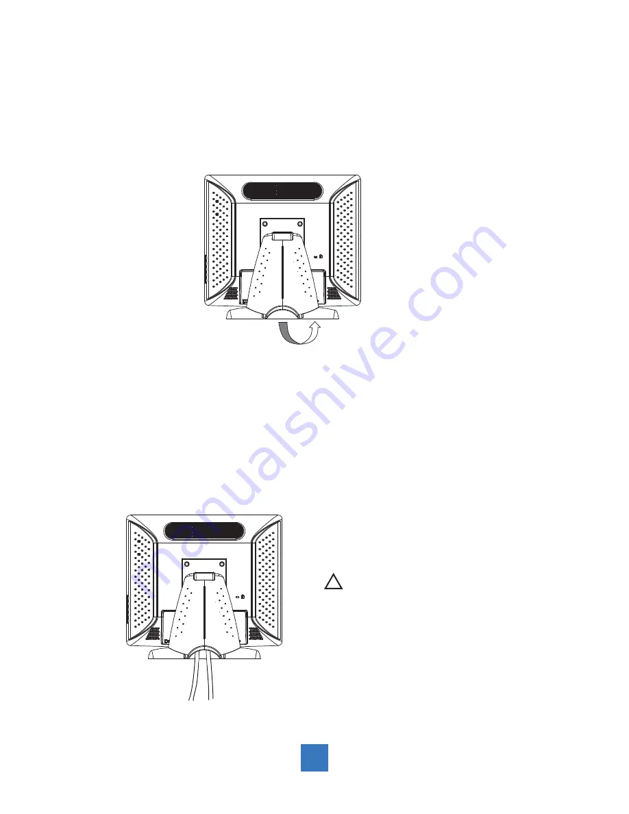
  Please follow these instructions to remove the cover on the back panel of the LCD  so that
  you can hookup the cables to associated connector.

Figure A

1.   To remove the back cover, follow the arrows in 

fi

 gure A and pull out with your  

fi

 ngers and 

       the cover should be removed from the stand.
2.   Follow the instructions on P.10 (Figure 11.1) to connect the cables to the appropriate
       connectors.
3.   Attach the cover back to the LCD stand by pressing 

fi

 rmly until the tabs snap into place.

      You may also keep the cables in order by using the cable organizer.

  !   

 Note!

You can place the LCD flat horizontally to 
make it easier to connect the cables. Please 
make sure that you place it on an even surface 
lest the LCD should be damaged by scratches 
or collision.

included cables organizer

8

Содержание TPM-193R

Страница 1: ...TPM 193 Series Touch Screen LCD Monitors USER s GUIDE...

Страница 2: ...n check WWW LAMPRECYCLE ORG The information contained in this document is subject to change without notice This document contains proprietary information that is protected by copyright All rights are...

Страница 3: ...nitor 7 Start Your Installation 8 Remove the Back Cover 8 Connecting the Display Figure 1 1 9 User Controls Front Panel Controls 11 How to Use the OSD Menus 12 On Screen Display Menus 13 Appendix Trou...

Страница 4: ...mercial cleaners or 50 50 mixture of water and isopropyl alcohol Use a soft cloth moistened with mild detergent to clean the display housing Use only high quality and safety approved AC DC adapter Dis...

Страница 5: ...nting solutions TPM 193R 5 wire resistive touch screen with dual RS 232 Serial USB controller TPM 193W SAW touch screen with USB controller TPM 193C Capactive touch screen with dual RS 232 Serial USB...

Страница 6: ...M 193C Analog capacitive touch screen for finger input only Surface Anti glare treatment Interface Dual RS 232 Serial USB controller Transmittance 85 5 Driver Windows VISTA XP 2000 ME 98 CE XP Embedde...

Страница 7: ...w LCD Display Power Cord VGA Signal Cable RS 232 Cable Quick Start Guide USB Cable A to B Audio in Cable DVI D Cable TPM 193X Series Only USB Cable A to A Option for MSR 4 TouchKit CD DC Power Supply...

Страница 8: ...Product Overview Front View TPM 193R TPM 193C Bottom View Without Stand RS 232 Option VGA IN AC IN Audio DVI IN USB DC IN TPM 193W Bottom View Without Stand VGA IN AC IN Audio DVI IN USB DC IN 5...

Страница 9: ...Kensington Security Slot The monitor can be secured to your desk or any other fixed object with Kensington lock security products The Kensington lock is not included 6...

Страница 10: ...onitor To mount the monitor on a swing arm or other mounting fixture follow the instructions included with the mounting fixture to be used please note to mount your monitor to the devices either mount...

Страница 11: ...e removed from the stand 2 Follow the instructions on P 10 Figure 11 1 to connect the cables to the appropriate connectors 3 Attach the cover back to the LCD stand by pressing firmly until the tabs sn...

Страница 12: ...dio out port of your computer 11 1 5 Connect the RS 232 or USB cable from the RS 232 or USB port of your display to the RS 232 port 11 1 or USB port 11 1 of your computer 6 Configure the touch screen...

Страница 13: ...Figure 11 1 10...

Страница 14: ...OSD 2 To increase value of the adjustment items 3 Select item clockwise Mute Minus 1 To decrease value of the adjustment items 2 Select item count clockwise Select Auto Adjust Select Select the adjust...

Страница 15: ...nitor has to be turned ON with a valid signal preset a Press and hold the Power and Menu key simultaneously for 1 seconds b The wording OSD Lock Power Lock will appear for 2 seconds on the monitor Thi...

Страница 16: ...al size 0 100 The ratio of dividing frequency of the dot clock is adjusted Fine 0 100 The phase of the dot clock is adjusted OSD Left Right 0 100 Adjusts the OSD menu screen position left or right OSD...

Страница 17: ...resolution of your computer to make it less than or equal to 1280 x 1024 Problem Image has vertical flickering line bars Use Fine to make an adjustment Check and reconfigure the display mode of the ve...

Страница 18: ...n powered on but it cannot receive any signal from the computer graphics card Check all the power switches power cables and VGA signal cable Going to sleep The LCD is under the power saving mode in ad...

Страница 19: ...Product Dimensions 438 00 67 90 267 40 405 50 370 00 Front View Side View Top View 16...

Страница 20: ...480 37 5 75 VESA SVGA 800 x 600 35 2 56 VESA SVGA 800 x 600 37 9 60 VESA SVGA 800 x 600 48 1 72 VESA SVGA 800 x 600 46 9 75 VESA XGA 1024 x 768 48 4 60 VESA XGA 1024 x 768 56 5 70 VESA XGA 1024 x 768...

Страница 21: ...connection follow the instructions below 1 Be sure that RS232 cable is connected from the computer 2 Power on the computer 3 Load the touch screen driver CD 4 Follow the step by step instructions as s...

Страница 22: ...193C Optional Capacitive Calibration Tool Install If you would like to use the Optional Capacitive Calibration Tool follow the instructions below 1 Load the driver CD to your CD Rom driver 2 Open the...

Отзывы: