background image


71 

GSM/GPRS/EDGE SIGNAL ANALYZER   


JD7105B Base Station Analyzer 


GSM


OTA


M

ODULATION 

A

NALYZER


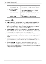
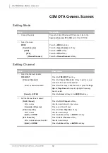
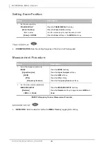
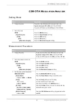
Setting Mode 

Step 

Description 

1. 

Connect the cable 

Connect an Omni/Directional RF Antenna to the to the 

Spectrum Analyzer RF In 50

 port of the JD7105B. 

Connect a GPS Antenna to the 

GPS

 port of the JD7105B. 

2. 

Select the mode 

MODE 

  [Signal Analyzer] 

    [GSM] 

      [OTA] 

        [Modulation Analyzer]


Press the 

MODE

 hard key. 

Press the 

Signal Analyzer

 soft key. 

Press the 

GSM

 soft key. 

Press the 

OTA

 soft key. 

Press the 

Modulation Analyzer

 soft key. 


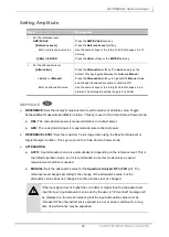
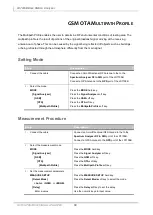
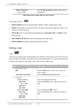
Measurement Procedure 

Step 

Description 

1. 

Connect the cable 

Connect an Omni/Directional RF Antenna to the to the 

Spectrum Analyzer RF In 50

 port of the JD7105B. 

Connect a GPS Antenna to the 

GPS

 port of the JD7105B. 

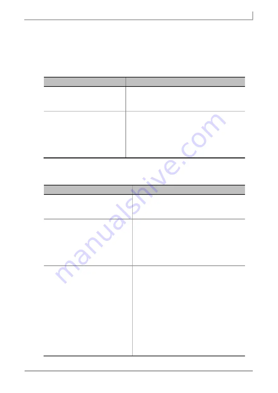
2. 

Select the measurement mode 

MODE 

  [Signal Analyzer] 

    [GSM] 

      [OTA] 

        [Modulation Analyzer]


Press the 

MODE

 hard key. 

Press the 

Signal Analyzer

 soft key. 

Press the 

GSM

 soft key. 

Press the 

OTA

 soft key. 

Press the 

Modulation Analyzer

 soft key. 

3. 

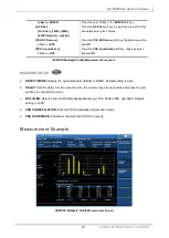
Set the measurement parameters 

MEASURE SETUP 

  [Detect Mode] 

    <Auto>

<GSM>

, or 

<EDGE> 

  [Delay] 

    Enter a value 

    [uSec] 

or

 ENTER 

  [FX Filter] 

    [No Filter]

[100K]

[200K]

,


    [400K (Default)]

, or

 [624K] 

  [PSK DC Remove] 

    <On> 

or

 <Off> 


Press the 

MEASURE SETUP

 hard key. 

Press the 

Detect Mode

 soft key to select the mode. 


Press the 

Delay

 soft key to set the delay. 

Use the numeric keys to input value. 

Press the unit soft key or the 

ENTER

 hard key. 

Press the 

FX


Filter

 soft key to select the internal RX filter 

bandwidth among the choices. 


Press the 

PSK DC Remove

 soft key. Toggle between 

On


and 

Off

Содержание JD7105B

Страница 1: ...ir measurement In this Chapter Using GSM GPRS EDGE Signal Analyzer 4 Display Overview 5 Connecting a Cable 7 Direct Connection 7 Indirect Connection 7 Over The Air OTA 8 Spectrum Analysis Measurement...

Страница 2: ...Setting External Clock 42 Measurement Procedure 43 Setting Limit 44 Measurement Example 46 Constellation Measurement 47 Setting Mode 47 Setting Frequency 47 Setting Amplitude 48 Setting Averaging 49...

Страница 3: ...etting Zoom Position 66 Measurement Procedure 66 Measurement Example 67 GSM OTA Multipath Profile 68 Setting Mode 68 Measurement Procedure 68 Measurement Example 69 GSM OTA Modulation Analyzer 71 Sett...

Страница 4: ...and applications It uses TDMA and 3 8 8PSK phase shift keying modulation The JD7105B performs measurements using the methods and limits as defined in the 3GPP TS 51 021 Base Station System BSS equipme...

Страница 5: ...nal offset Reference setting information Frequency Trigger Measurement Setting Information Spectrum Analyzer Operation Mode Information Displays the operation mode of spectrum analyzer Sweep or FFT De...

Страница 6: ...to 6 markers Screen Menu Title Screen Menu and Sub menu Scale Unit Information dBm dBmV dBuV V and W User Input Window Activates when user input menu or key is selected Pressing PREV hard key will ca...

Страница 7: ...ection Monitor Port and RF In Port Connection The maximum power for the Spectrum Analyzer RF In 50 port is 30 dBm 1 Watt If the input signal level to be measured is greater than 30 dBm use a High Powe...

Страница 8: ...imum power for the Spectrum Analyzer RF In 50 port is 30 dBm 1 Watt If the input signal level to be measured is greater than 30 dBm use a High Power Attenuator to prevent damage when you directly conn...

Страница 9: ...or Channel Number Enter a value Forward or Reverse Press the FREQ DIST hard key Press the Center Frequency soft key Use the numeric keys the rotary knob or the arrow keys When using the numeric keys...

Страница 10: ...g step size of the Channel Number when using the rotary knob or the arrow keys The step size can be entered by using numeric keys and the Enter soft key CHANNEL STANDARD When the channel standard is s...

Страница 11: ...nce level changes according to the change of the attenuator s value but the attenuator s value does not change when the reference level is changed If the input signal level is higher than 30 dBm or hi...

Страница 12: ...er 1 key in the numeric keypad Press the Sweep Mode soft key Toggle between Continue and Single Setting Trace and Display TRACE DISPLAY SELECT TRACE Selects an active trace from T1 to T6 Trace numbers...

Страница 13: ...isplay screen CAPTURE Captures a current trace on the display screen with the selected trace number TRACE VIEW Displays the trace of the selected trace number on the display screen or hides it from th...

Страница 14: ...ber between 1 and 6 DELTA This Delta marker type is associated with a Normal marker A Normal marker must be set before a Delta marker is set When the Delta marker is set the position set by the Delta...

Страница 15: ...es the active marker to the second highest peak of the trace NEXT PEAK RIGHT Moves the active marker to the highest peak to the right of its current position NEXT PEAK LEFT Moves the active marker to...

Страница 16: ...uency FREQ DIST Center Frequency Enter a value GHz MHz kHz or Hz or Channel Number Enter a value Forward or Reverse Press the FREQ DIST hard key Press the Center Frequency soft key Use the numeric key...

Страница 17: ...TEP Defines the moving step size of the Channel Number when using the rotary knob or the arrow keys The step size can be entered by using numeric keys and the Enter soft key CHANNEL STANDARD When the...

Страница 18: ...nce level changes according to the change of the attenuator s value but the attenuator s value does not change when the reference level is changed If the input signal level is higher than 30 dBm or hi...

Страница 19: ...is the number 1 key in the numeric keypad Press the Sweep Mode soft key Toggle between Continue and Single Setting Trigger Source TRIGGER This hot key is used to select the trigger source among RF Bu...

Страница 20: ...is relative to the peak of the signal RF Burst is also known as RF Envelope INTERNAL FB FREE BURST Sets the trigger level to FB if there is a frequency burst signal RF BURST TS TRAINING SEQUENCE Sets...

Страница 21: ...ge power level above the threshold is then computed and displayed Measurement Procedure Step Description 1 Connect the cable Connect the cable to the Spectrum Analyzer RF In 50 port of the JD7105B and...

Страница 22: ...or ENTER Press the Test Limits soft key to toggle between On and Off and select one Press the High Limit soft key to set the upper limit of the Pass Fail criteria Use the numeric keys to input value...

Страница 23: ...r s X and Y coordinates may be slightly different for each measurement mode and refer to the description of each measurement There are three different marker types available Normal Delta and Delta pai...

Страница 24: ...e position of the Normal marker and the marker s X and Y values displays the difference compared with the Delta Pair marker The reference position will be varied in accordance with trace change MARKER...

Страница 25: ...alue uSec or ENTER RX Filter No Filter 100K 200K 400K Default or 624K Press the MEASURE SETUP hard key Press the Delay soft key to set the delay Use the numeric keys to input value Press the unit soft...

Страница 26: ...ct one Press the High Limit soft key to set the upper limit of the Pass Fail criteria Use the numeric keys to input value Press the unit soft key to select 3 Enable beep LIMIT Beep On or Off Press the...

Страница 27: ...position can be set manually by entering numeric values frequency when one of the marker types is selected SELECT MARKER Selects an active marker whose position can be changed with the rotary knob or...

Страница 28: ...strument displays those markers back at the previous position If a measurement mode is changed current settings are not restored MARKER Sets the X coordinate of the active marker as selected MARKER CE...

Страница 29: ...elect the Signal Analyzer mode Press the GSM soft key Press the RF Analysis soft key Press the Spectrum Emission Mask soft key 3 Set the measurement parameters MEASURE SETUP Delay Enter a value uSec o...

Страница 30: ...rum Emission Mask Press the LIMIT hot key It is the number 7 key in the numeric keypad Press the RF Test Limits soft key Press the Spectrum Emission Mask soft key 2 Set the limit Test Limits On or Off...

Страница 31: ...er position can be set manually by entering numeric values frequency when one of the marker types is selected SELECT MARKER Selects an active marker whose position can be changed with the rotary knob...

Страница 32: ...d in accordance with trace change MARKER ALL OFF Turns all the markers the screen off When the Marker View is selected for those markers the instrument displays those markers back at the previous posi...

Страница 33: ...er mode Press the GSM soft key Press the RF Analysis soft key Press the Spurious Emissions soft key 3 Set the measurement parameters MEASURE SETUP Range Table Range Enter a value Enter Start Frequency...

Страница 34: ...for the selected range number in the Range menu Use the numeric keys to enter a value and press one of the unit soft keys STOP FREQUENCY Sets or changes the stop frequency value to be measured for the...

Страница 35: ...ot key It is the number 7 key in the numeric keypad Press the RF Test Limits soft key to enable or disable test limits on RF Analysis measurements Press the Spurious Emissions soft key 2 Set the limit...

Страница 36: ...position can be set manually by entering numeric values frequency when one of the marker types is selected SELECT MARKER Selects an active marker whose position can be changed with the rotary knob or...

Страница 37: ...d in accordance with trace change MARKER ALL OFF Turns all the markers the screen off When the Marker View is selected for those markers the instrument displays those markers back at the previous posi...

Страница 38: ...measurement provides the followings P vs T Slot P vs T Frame Setting Mode Step Description 1 Connect the cable Connect the signal to the Spectrum Analyzer RF In 50 port using the cable whose loss was...

Страница 39: ...he rotary knob or the arrow keys the channel changes in a predefined channel step The channel step can be configured by selecting the Channel Step soft key FREQUENCY STEP Defines the moving step size...

Страница 40: ...the screen indicating that the input attenuation value must be increased When the instrument is exposed to an over power condition for a long time its performance may be degraded PREAMP Turns on or o...

Страница 41: ...is the number 1 key in the numeric keypad Press the Sweep Mode soft key Toggle between Continue and Single Setting Trigger Source TRIGGER This hot key is used to select the trigger source among RF Bu...

Страница 42: ...chronized with the Base Station When an external clock is not supplied the JD7105B works with a built in internal high accuracy time base In this case some measurement results may exhibit inaccurate v...

Страница 43: ...measurement parameters MEASURE SETUP Detect Mode Auto GSM or EDGE Delay Enter a value uSec or ENTER RX Filter No Filter 100K 200K 400K Default or 624K PSK Constellation On or Off PSK DC Remove On or O...

Страница 44: ...lue dBm or ENTER Frame Average Power Test Limits On or Off High Limit Enter a value dBm or ENTER Low Limit Enter a value dBm or ENTER Press the Burst Power soft key Press the Test Limits soft key to t...

Страница 45: ...y to complete the input LOW LIMIT Sets the lower limit of the Pass Fail criteria Use the numeric keys to enter a threshold or limit value and press the dBm unit soft key or the ENTER hard key to compl...

Страница 46: ...GSM GPRS EDGE SIGNAL ANALYZER 46 JD7105B Base Station Analyzer Measurement Example GSM Power vs Time Slot Measurement Screen GSM Power vs Time Frame Measurement Screen...

Страница 47: ...ncy Step Description 1 Set the frequency FREQ DIST Center Frequency Enter a value GHz MHz kHz or Hz or Channel Number Enter a value Forward or Reverse Press the FREQ DIST hard key Press the Center Fre...

Страница 48: ...size of the Channel Number when using the rotary knob or the arrow keys The step size can be entered by using numeric keys and the Enter soft key CHANNEL STANDARD When the channel standard is selected...

Страница 49: ...ondition for a long time its performance may be degraded PREAMP Turns on or off the internal pre amplifier The pre amplifier is to amplify a low level input signal This soft key toggles between the On...

Страница 50: ...he user input window must be inactive first to get the Sweep hot key function other than the number input SWEEP MODE Sets the sweep method Toggle between Continue and Single Step Description 1 Set the...

Страница 51: ...chronized with the Base Station When an external clock is not supplied the JD7105B works with a built in internal high accuracy time base In this case some measurement results may exhibit inaccurate v...

Страница 52: ...NTER RX Filter No Filter 100K 200K 400K Default or 624K PSK DC Remove On or Off PSK Constellation On or Off Press the MEASURE SETUP hard key Press the Detect Mode soft key to select the mode Press the...

Страница 53: ...ber 7 key in the numeric keypad Press the Modulation Test Limits soft key 2 Set the limit Frequency Error Test Limits On or Off High Limit Low Limit Phase Error RMS Test Limits On or Off High Limit Lo...

Страница 54: ...to complete the input LOW LIMIT Sets the lower limit Use the numeric keys to input value and press the unit soft key or the ENTER hard key to complete the input PHASE ERROR RMS Sets the RMS of the pha...

Страница 55: ...PEAK Sets the peak of the error vector magnitude which is measured and calculated over the useful part of the burst and is shown as a percentage TEST LIMITS Enables or disables the test limit s Toggl...

Страница 56: ...GSM GPRS EDGE SIGNAL ANALYZER 56 JD7105B Base Station Analyzer Measurement Example GSM Constellation Measurement Screen...

Страница 57: ...sis OTA provides the following measurements Channel Scanner Frequency Scanner Multipath Profile Modulation Analyzer Setting Mode Step Description 1 Connect the cable Connect an Omni Directional RF Ant...

Страница 58: ...frequency changes in a predefined frequency step The frequency step can be configured by selecting the Frequency Step soft key CHANNEL NUMBER Enters a channel number and selects the Forward or Reverse...

Страница 59: ...ttenuator s value does not change when the reference level is changed If the input signal level is higher than 30 dBm or higher than the allowable mixer input limit per input attenuator s value set by...

Страница 60: ...de SWEEP This hot key is used to set the sweep parameters The user input window must be inactive first to get the Sweep hot key function other than the number input SWEEP MODE Sets the sweep method To...

Страница 61: ...xternal Ref Clock Ext Ref SMA Automatic switching Input signal level 3 dBm External GPS GPS Clock GPS SMA Automatic switching GPS signal received PP2S Internal Internal Trigger Default External Extern...

Страница 62: ...ENTER Press the FREQ DIST hard key Press the Channel Standard soft key to get the pop up window of the channel standard list Press the arrow keys rotate the knob or press the Page Up and Page Down so...

Страница 63: ...e numeric keys and the input is completed by pressing the Enter soft key or ENTER hard key CHANNEL STANDARD When the channel standard is selected from the list the start frequency information on the d...

Страница 64: ...e measurement parameters MEASURE SETUP Detector RMS or Peak Press the MEASURE SETUP hard key Press the Detector soft key to toggle between RMS and Peak GSM OTA Channel Scanner Measurement Procedure ME...

Страница 65: ...nels Enter a value between 8 and 64 Enter or ENTER Press the FREQ DIST hard key Press the Start Frequency soft key Use the numeric keys Press the unit soft key to complete the input Press the of Chann...

Страница 66: ...ess the Frequency Scanner soft key 2 Set the measurement parameters MEASURE SETUP Detector RMS or Peak Press the MEASURE SETUP hard key Press the Detector soft key to toggle between RMS and Peak GSM O...

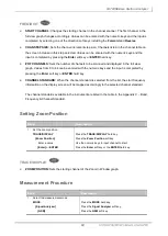
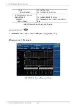
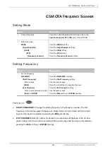
Страница 67: ...67 GSM GPRS EDGE SIGNAL ANALYZER JD7105B Base Station Analyzer Measurement Example GSM OTA Frequency Scanner Measurement Screen...

Страница 68: ...mode MODE Signal Analyzer GSM OTA Multipath Profile Press the MODE hard key Press the Signal Analyzer soft key Press the GSM soft key Press the OTA soft key Press the Multipath Profile soft key Measu...

Страница 69: ...stellation soft key Toggle between On and Off GSM OTA Multipath Profile Measurement Procedure MEASURE SETUP DETECT MODE Selects the signal standard of GSM or EDGE Default setting is Auto DELAY Sets th...

Страница 70: ...na is supplied and locked to the satellites the positioning information including longitude latitude and the number of tracked satellites will be displayed on the bottom of the screen GPS Indicator De...

Страница 71: ...50 port of the JD7105B Connect a GPS Antenna to the GPS port of the JD7105B 2 Select the measurement mode MODE Signal Analyzer GSM OTA Modulation Analyzer Press the MODE hard key Press the Signal Ana...

Страница 72: ...SK DC removal Setting Limit LIMIT This hot key is used to set the threshold value for the limit line on the display screen It turns on or off the limit or band limit settings of the measurement for pa...

Страница 73: ...n and Off 3 Enable beep LIMIT Beep On or Off Press the LIMIT hot key It is the number 7 key in the numeric keypad Press the Beep soft key to toggle between On and Off and select one This will make aud...

Страница 74: ...put EVM RMS Sets the RMS of the error vector magnitude which is measured and calculated over the useful part of the burst and is shown as a percentage TEST LIMITS Enables or disables the test limit s...

Страница 75: ...ut Measurement Example GSM OTA Modulation Analyzer Measurement Screen POSITIONING INFORMATION If a GPS antenna is supplied and locked to the satellites the positioning information including longitude...

Отзывы: