background image

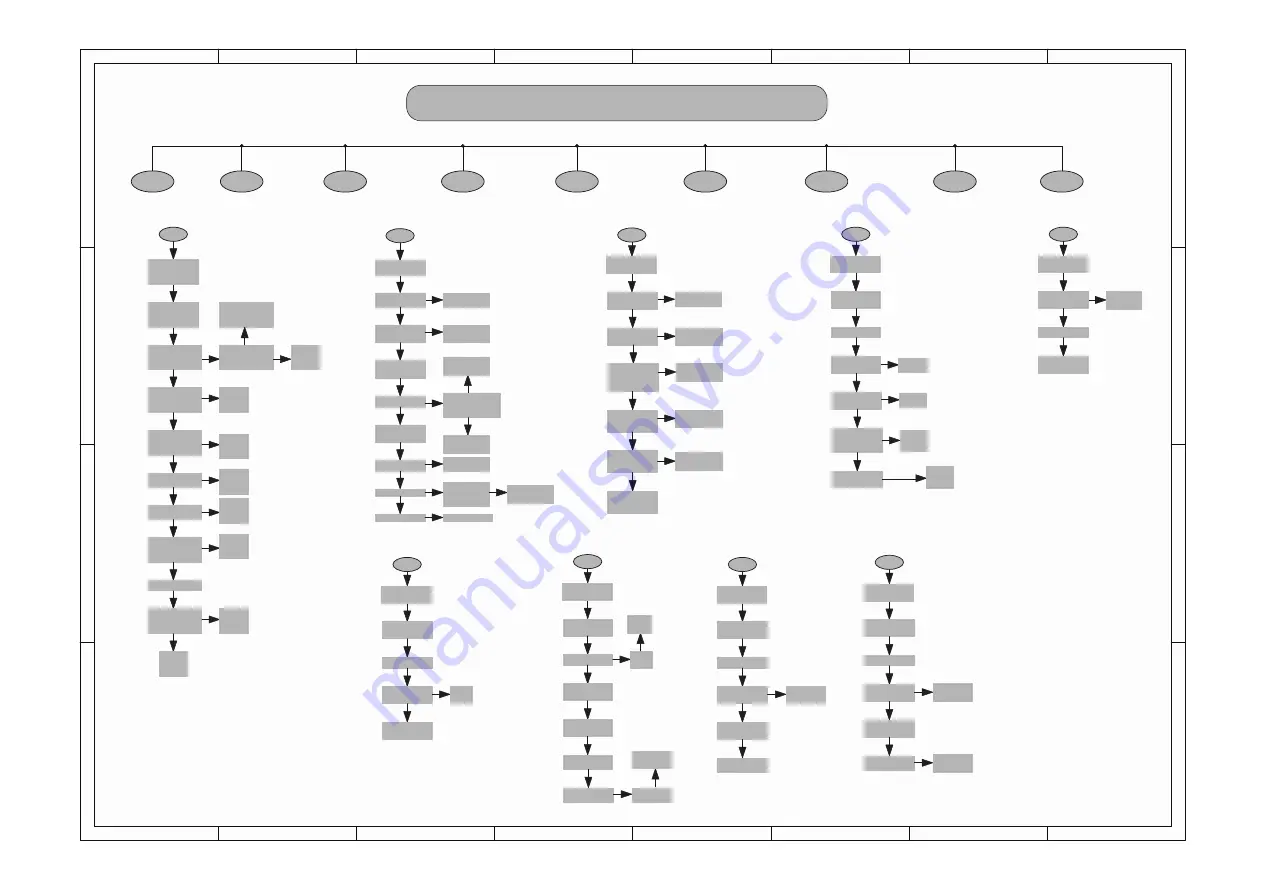
Party Box  On The Go REPAIR CHART

A

OK

NG

A

NO POWER

B

NO KEY FUNCTION

C

Function Indicator RGB LED no light up

D

Bluetooth Pairing Failure

Bluetooth(No sound

˅

E

F

AUX IN (No Sound

˅

B

OK

G

USB IN (No Sound

˅

H

Wire_MIC/Guitar(No Sound

˅

I

Wireless MIC (No Sound

˅

Check the Main CN100 

Pin 1/2/3 power output 
at 18V

[Refer to check point 

ķ

Connect the AC cord
,Press the Power button 

on the unit to turn on 

the unit.

LED not light up.

Check the cable is 

connected correctly
 (Main CN100 to Power 

CN902)

Connect correctly or 

change the cable

NG

OK

Change

Mainboard  
PCB

OK

Check the Main C110 or 

TP101 for 5.1V
[Refer to check point 

ĸ

]

NG

Check the Main C115 or 
TP102 for 3.3V

[Refer to check point 

Ĺ

OK

NG

OK

Check the Main C127 

for 1.25V

OK

Check the Main  CN403 

Pin 5 for 3.3V

Change

Mainboard  

PCB

NG

NG

OK

Check the cable is 

connected correctly 

(Main CN403 to LED 

CN752)

Connect 

correctly or 

change the 

cable

NG

OK

Change LED PCB Unit

NG

Check the cable is 

connected correctly 

(Main CN400 to LED  
J750)

OK

NG

Change

Mainboard  

PCB

Change
Mainboard  

PCB

Change

Mainboard  
PCB

Change

Mainboard  
PCB

Connect 

correctly or 

change the 
cable

Connect the AC mains 

lead

Press “Power” button to 
Power ON unit

Go to “No Power

NG

OK

Check the Main C410 
at BK3.3V  C411 at 

S3.3V C412 at 18V

Change mainboard 
pcb

NG

OK

BK3.3V at Pin 5 S3.3V 

at PIN6 +18V at PIN7

of Main CN403

OK

S3.3 V at Pin 6

Of LED CN403

OK

Check the Main C410 

at BK3.3V  C411 at 

S3.3V C412 at 18V

OK

S3.3 V at Pin 6

of LED CN752

OK

The KEY board no S3.3 

OK

Change KEY PCB  

NG

Change Main PCB  

Check the cable is 

connected correctly (Main  

CN403 to Keyboard 

CN752)

NG

NG

Connect correctly or 

change the cable

Change mainboard 

pcb

Change

Keyboard PCB Unit 

NG

OK

Check the cable is 

connected correctly 

(Mainboard CN403 to 
Keyboard CN752)

NG

NG

Connect correctly or 

change the cable

C

OK

Press the Power button 

on the unit to turn on 

the unit.

Go to 

“No Key Function”

NG

Press and hold =1S[      

] button on the unit to 

select “BLUETOOTH”.

OK

The Bluetooth White 

LED is fast flashing

Go to “Function 

indicator White LED 

no light up”

NG

Using the smartphone 

to search the 
BLUETOOTH which 

named “Party Box On  

the Go”

Change 

Bluetooth Model

NG

OK

Connection of 
Bluetooth® device

(The Bluetooth LED is 

lighted

Change 
Keyboard PCB Unit

OK

NG

Sound output

OK

Go to
“No Sound 

(Bluetooth®)”

NG

No problem found

OK

D

OK

Press the Power button 
on the unit to turn on 

the unit.

Change

Main PCB 

NG

Press [LightSwitch] 

button on the control.

.

OK

Connect  BTor AUX IN

OK

Sound can control 

different  lighting  
effects

OK

Check the Main C431 

or  C432 at “5.0V” 

Change

Main PCB 

NG

OK

Check the cable is 
connected correctly 

(Main CN401 to LED  

CN1000)

Connect 

correctly or 

change the 

cable

NG

OK

Change LED PCB Unit

Change

Main PCB 

Still No Display

E

OK

Press the Power button 
to turn on the unit.

Go to 

“Bluetooth® 

Pairing failure”

NG

Connect 

Bluetooth® device

OK

Playback No sound

OK

Change

Bluetooth Model

F

Press the Power button 

to turn on the unit 

Select “AUX IN” 

source  

No Sound 

output

Change
AUX IN Cable

NG

Still 

No Sound 

output

Change

Main PCB 

OK

G

Press the Power button 

to turn on the unit 

Select “USB” source

There are songs in the 
Device’s root directory

The indicator light of 

the USB source is 

always on

Press [ play/stop  ] 

button

Change 
the USB  

Device

OK

NG

NG

Change 

Mainboard 
pcb

No Sound 

output

Change the USB  

Device

Still  No Sound 

output

Change 

Mainboard pcb

OK

H

Press the Power button 

to turn on the unit 

Select “MIC/Guitar

” source

No Sound output

Change the Wire MIC

Still No Sound output

OK

Change

Main PCB 

Change keyboard 

pcb

OK

I

Press the Power button 
to turn on the unit 

Select “Wireless MIC” 

source

Connection the 

Wireless Mic

No sound output

Adjust
The Wireless

Rotary knob

OK

No sound output

Change the 

Wireless MIC

OK

Change Wireless 

RX Model PCB

OK

Trouble Shooting   

9

Содержание Partybox On-The-Go

Страница 1: ...S2 JBLPARTYBOXONTHEGOBR2 JBLPARTYBOXONTHEGOAS3 CONTENTS Safety Instruction 2 Technical Specifications 5 Software upgrade Instruction Reset Procedure 8 Troubleshooting Charts 9 Disassembly Instruction...

Страница 2: ...U V T R P O Q P V Q X T O Q U V P Y Y Z W Q P V Y O a U R S R S O U V T R W X Y R U Z V T s o P i Y P X T O S P W o p X U V R O W p O W O V Y O R Z W P Q U Z Y Z o o X V U Y P R U Z V T M _ Z a O m O...

Страница 3: ...U WR DSSO LQJ SRZHU WR WKH XQLW XQGHU WHVW IWHU UHPRYLQJ DQ HOHFWULFDO DVVHPEO HTXLSSHG ZLWK 6 GHYLFHV SODFH WKH DVVHPEO RQ D FRQGXFWLYH VXUIDFH VXFK DV DOXPLQXP IRLO WR SUHYHQW HOHFWURVWDWLF FKDUJH E...

Страница 4: ...H DSSOLDQFH LQSXW RXWSXW WHUPLQDOV VFUHZKHDGV PHWDO RYHUOD V FRQWURO VKDIW HWF 3OXJ WKH OLQH FRUG RI WKH DSSOLDQFH GLUHFWO LQWR D 9 RXWOHW DQG WXUQ WKH SRZHU VZLWFK RQ Q FXUUHQW PHDVXUHG PXVW QRW H FH...

Страница 5: ...d Output Power with 5 THD Woofer 40W x 1 tweeter 15W x2 with AC mode Woofer or Tweeter drive when measure power Woofer 1kHz Tweeter 10kHz time 1 minute Input Sensitivity Analog 3 5mm aux_in 370mV 10 D...

Страница 6: ...ronmental Conditions The unit should work between 5 C till 45 C under ambient temperature The unit should not get damaged within the temperature range of 5 C till 60 C ambient temperature 4 1 3 Microp...

Страница 7: ...40KHz 175KHz 115KHz 0 8 4 2 3 Receiver Performance Description Specification Single Slot Sensitivity 0 1 BER 85dBm Multiple Slot Sensitivity 0 1 BER 85dBm Maximum Input Level 0 1 BER 20dBm 4 2 4 Trans...

Страница 8: ...4 The white LED will be off after finish update It s takes 10 15 seconds minutes to finish update 5 Plug out USB the main unit will auto reboot 1 Power on main unit 2 long press button volume play key...

Страница 9: ...or change the cable C OK Press the Power button on the unit to turn on the unit Go to No Key Function NG Press and hold 1S button on the unit to select BLUETOOTH OK The Bluetooth White LED is fast fl...

Страница 10: ...6 8 7 5 3 1 4 2 Figure 2 Figure 3 Disassembly the 5pcs screw from the leather back shell and open Figure 4 Disassembly the rear cover 10pcs screw Figure 5 Disassembly 8PCS screws from left and right s...

Страница 11: ...2 3 4 1 3 2 4 5 Figure 8 Take 4pcs side rubber from right side cover and open screws Figure 9 Take 4pcs side rubber from left side cover and open screws Figure 10 Take the top cover nut washev Figure...

Страница 12: ...en wireless mic screws Figure 14 Figure 15 Dismantling of JK PCBA Open jk PCBA screws Figure 16 Open speaker drivers screws Figure 17 Dismantling of lighting PCBA Open lighting PCBAS screws Dismantlin...

Страница 13: ...ND 8 19V 30PIN 0 5mm 1 AD_KEY1 2 AD_KEY2 30 WM2_SDA 5PIN 1 25 3 GND 4 5V 5 5V D_AMP TAS5825P P 3 3V 18V SPK_OUT BTL THD 1 3 30W Woofer BCK LRCK DATA0 L R DATA2 C SUB A5V Switch SGM48754 A3 3V S 3 3V P...

Страница 14: ...r button GND W_Mute Wireless_TX Wireless_RX GND RX GND TX CTS RTS RSR SCL SDA 3 3V 1 2 3 4 5 6 1 2 3 4 5 1 2 3 4 5 6 1 2 3 4 5 6 1 2 3 4 5 6 7 8 9 10 11 12 CN402 CN101 CN211 CN401 CN100 CN403 CN400 Ma...

Страница 15: ...7 0 1uF 50V C249 0 1uF 50V C243 0 1uF 50V C244 1uF 6 3V C248 0 01uF 50V C245 0 1uF 50V C250 NC C252 22pF 50V C255 22pF MC MC 50V C256 0 1uF 50V C231 0 1uF 50V C253 0 1uF 50V C257 0 1uF 50V C232 0 1uF...

Страница 16: ...01 TP100 M208 M206 M207 R356 R355 R354 R353 R352 R351 R350 R349 R347 R345 R344 R343 R340 R339 R338 R331 R330 R329 R328 R327 R326 R325 R319 R318 R317 R316 R315 R314 L304 C349 C348 C347 C346 C345 C344 C...

Страница 17: ...D100 D102 D104 D108 D109 FB201 FB210 FB101 FB404 FB408 FB409 FB410 FB411 FB412 FB102 FB413 FB414 FB415 FB416 FB417 FB418 FB419 FB420 FB421 FB422 FB423 FB426 FB429 FB105 FB106 FB430 FB431 FB433 FB104 F...

Страница 18: ...1 1M R903 1M R915 NC V C916 104 R929 1 5K R934 24K 1 R917 10 C911 104 R932 5K6 R928 8 2K ZD903 4 3V C912 104 TVR901 TVR14D561 R933 4 99K 1 RNT004002 5090 NTC901 SCK0504 KOF020104 0190 F901 T3 15AL 250...

Страница 19: ...R933 R932 R931 R930 R929 R928 R927 R926 R925 R924 R923 R922 R920 R919 R918 R917 R916 R913 R914 R912 R911 R910 R909 R908 R907 R906 R905 R904 R903 R902 R901 P905 P902 P901 IC903 IC902 IC901 FB901 D904...

Страница 20: ...am TOP view PSU PCBA 20 C915 H902 D905 CE901 G902 G901 FB903 TVR901 T901 R921 Q901 NTC901 LF902 LF901 L901 H901 FB902 F901 CY902 CY901 CN902 CN901 C917 C908 C904 C905 BD901 CX901 CX902 CY903 CY904 GT9...

Страница 21: ...53 CN6 20 CN751 CN6 20 Guitar Mic Control_1 14 Guitar Mic Control_1 18 LED RST BASS_LED BASS_LED S3V3 C754 104 C753 104 C752 104 C751 104 C750 104 28 W_MUTE 27 GND C859 22uF 10V C805 22uF 10V S3V3 BK3...

Страница 22: ...755 C756 C757 C770 C772 C775 C776 C771 C777 C779 C781 C773 C791 C793 C794 C795 C796 C797 C798 C799 C800 C802 C805 C806 C807 C804 C814 C815 C816 C817 C844 C836 C853 C855 C857 C858 C859 C860 C861 C862 C...

Страница 23: ...FB786 FB775 IC756 IC754 L750 LD753 LD755 LD754 LD756 LD757 LD758 LD759 R750 R751 R752 R753 R754 R755 R757 R759 R760 R761 R808 R801 R811 R812 R805 R809 R807 R814 R815 R817 R816 R819 R823 R820 R826 R79...

Страница 24: ...3 LED1006 SMD LED GND 1 DIN 2 DOUT 4 VDD 3 LED1007 SMD LED R1000 2 2R R1001 2 2R R1007 2 2R R1002 2 2R R1003 2 2R R1004 2 2R R1005 2 2R R1006 2 2R VDD VDD C1010 104 GND GND A1 FB1009 FB_0603_600 FB10...

Страница 25: ...02 R1007 L E D 1 0 2 5 L E D 10 2 4 LED10 23 LED10 22 LE D1 02 1 L E D 1 0 2 0 LED1019 LED1018 LED1017 LED1016 LED1015 LED1014 LED1013 L E D 1 0 1 2 L E D 10 11 LED101 0 LED10 09 LE D1 00 8 L E D 1 0...

Страница 26: ...Layout Diagram Bottom View MIC PCBA 26 VR700 JK700 J700 FB704 FB703 FB701 FB700 D703 D702 D701 D700 C703 C702 C701 C700 Layout Diagram TOP View MIC PCBA...

Страница 27: ...tom View USB AC AUX JAKE PCBA 27 J751 J752 JK750 P750 C 7 5 0 C 7 5 1 C 7 5 2 C 7 5 3 C 7 5 4 C 7 5 5 F B 7 5 0 F B 7 5 1 F B 7 5 2 J 7 5 0 Z D 7 5 0 C 7 5 6 C 7 5 7 C 7 5 8 Layout Diagram TOP View US...

Страница 28: ...RTYBOXGO 1 EA 28 ABN100008 0305 REAR SEALING COVER PARTYBOXGO 1 EA 29 ABN100008 0323 RUBBER CONNECTOR PARTYBOXGO 1 EA 30 WMA100103 0001 REAR COVER ASSY PARTYBOXGO 1 EA 31 BPV100184 00AA SIDE COVER L A...

Страница 29: ...20 GAL100602 0001 AL HOOK PIPE AL ALLOY 6063 PARTYBOXGO 2 EA 21 WMA100098 0001 P TUBE R ASM PARTYBOXGO 1 EA 22 ABN115190 0001 MAIN PCB PARTYBOXGO 1 EA 23 ABN115170 0001 POWER PCB CEM PARTYBOXGO 1 EA 2...

Страница 30: ...0080 POWER CORD IN PARTYBOXGO 1 EA VPA002203 0140 POWER CORD AM BR PARTYBOXGO 1 EA VPE003209 0040 POWER CORD BR2 PARTYBOXGO 1 EA VFC100221 070R FFC CABLE 10P 70MM 60VPARTYBOXGO 1 EA VFC300221 190R FF...

Страница 31: ...REVISION LIST Version 1 0 Date 2020 06 10 Initial release Version 1 1 Date 2021 01 07 Update Spare Part List 31...

Отзывы: