4
CONNECTIONS
Step 3
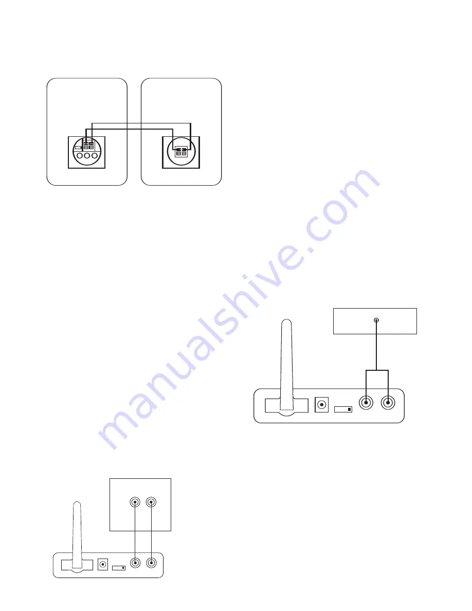
Connect the speaker wire (included) to the push terminals on the Active
Speaker
5
and the push terminals on the rear of the Passive Speaker. See
figure 4 .
Step 4
Plug the Transmitter Module and Active Speaker into the wall outlet. Make
sure the transmitter’s antenna
A
is extended upwards.
Step 5
If necessary, configure your A/V receiver to activate the pre-amp level outputs
for the surround/rear channels. (Consult your receiver’s owner’s manual for
specific instructions.)
When connected properly, the top LED on the front of the Active Speaker
should be green. The bottom LED should flash green until the Transmitter and
Active Speaker “lock in”. It will then illuminate solid green also.
Application 2
Adding speakers to remote locations around your home
Determine if your receiver contains pre-amp outputs for front/main channels,
usually indicated by RCA type jacks on the back of the receiver labeLED as
pre-out. (Please refer to your receiver’s owner’s manual to confirm whether it
includes pre-amp outputs.) If your receiver includes these outputs, follow the
steps in CONNECTION OPTION A. If not, then you may hook the JBL OnAir
Control 2.4G to your portable audio player or computer through their head-
phone jacks as described in CONNECTION OPTION B.
NOTES:
Make sure power is turned off on all components.
Some computer sound cards also contain pre-amp outputs, if you would like to
connect the computer to the JBL OnAir Control 2.4G using pre-amp outputs on
you computer, follow the steps in CONNECTION A.
CONNECTION OPTION A
Connecting using the pre-amp outputs on your receiver
Step 1
Connect the interconnect cable (included) to the left and right front/main pre-
amp outputs or zone 2 outputs or REC Outputs and the inputs on the
Transmitter Module
D
as shown in figure 5.
INPUT
RL
R
L
ID
CODE
1 234
RECEIVER
Front/Main/Second Room
Pre-Amp Outputs
ID
CODE
1 234
DC 20V SUB OUT LINE IN
LEFT CHANNEL SPEAKER
TO RIGHT SPEAKER
+
–
RIGHT CHANNEL SPEAKER
TO LEFT SPEAKER
+
–
Step 2
Place the Active Speaker in the desired location in your home near an AC out-
let, as it needs to plug in to the wall.
Step 3
Connect the speaker wire (included) to the push terminals on the Active
Speaker
5
and the push terminals on the rear of the Passive Speaker
9
as
shown in figure 4 .
Step 4
Plug the Transmitter Module and Active Speaker into the wall outlet. Make
sure the transmitter’s antenna
A
is extended upwards.
Step 5
If necessary, configure your receiver to activate the pre-amp level outputs for
the main/front channels. (Consult your receiver’s owner’s manual for specific
instructions.)
When connected properly, the top LED on the front of the Active Speaker
should be green. The bottom LED should flash green until the Transmitter and
Active Speaker “lock in”. It will then illuminate solid green also.
CONNECTION OPTION B
Connecting using the headphone jack on your portable audio player or
computer
NOTES:
Make sure power is turned off on all components.
Some computer sound cards also have external speaker outputs, this connec-
tion may be used instead of the headphone jack if desired.
Step 1
Connect the RCA – 1/8” mini jack cable (included) to the headphone output of
your portable audio player and the inputs on the Transmitter Module
D
as
shown in figure 6.
Step 2
Place the Active Speaker in the desired location in your home near an AC out-
let, as it needs to plug in to the wall.
Step 3
Connect the speaker wire (included) to the push terminals on the Active
Speaker
5
and the push terminals on the rear of the Passive Speaker as
shown in figure 4.
Step 4
Plug the Transmitter Module and Active Speaker into the wall outlet. Make
sure the transmitter’s antenna
A
is extended upwards.
When connected properly, the top LED on the front of the Active Speaker
should be green. The bottom LED should flash green until the Transmitter and
Active Speaker “lock in”. It will then illuminate solid green also.
INPUT
RL
ID
CODE
1 234
Portable Audio Device or
Computer Headphone Jack (1/8") mini
Содержание On Air Control 2.4G
Страница 1: ...CONTROL 2 4G ON AIR OWNER S GUIDE...


