I n p u t C o n n e c t i o n s
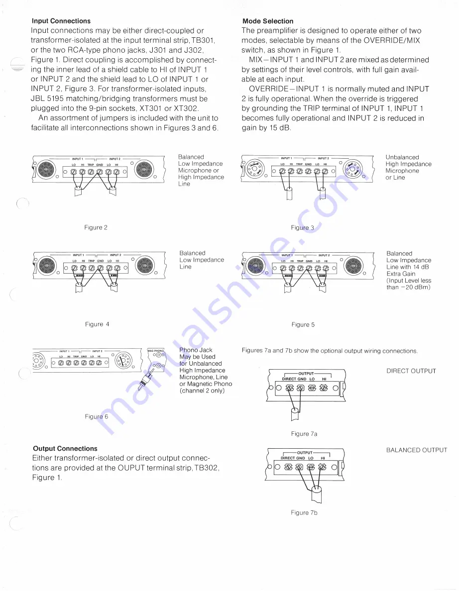
Input connections may be either direct-coupled or
transformer-isolated at the input terminal s t r i p , T B 3 0 1 ,
or the two RCA-type phono j a c k s , J 3 0 1 and J 3 0 2 ,
Figure 1. Direct coupling is a c c o m p l i s h e d by connect-
ing the inner lead of a shield cable to HI of I N P U T 1
or I N P U T 2 and the shield lead to L O of I N P U T 1 or
I N P U T 2, Figure 3. For transformer-isolated inputs,
J B L 5195 matching/bridging transformers must be
plugged into the 9-pin sockets, X T 3 0 1 or X T 3 0 2 .
An assortment of j u m p e r s is included with the unit to
facilitate all interconnections s h o w n in Figures 3 and 6.
M o d e S e l e c t i o n
T h e preamplifier is designed to operate either of two
modes, selectable by m e a n s of the O V E R R I D E / M I X
switch, a s s h o w n in Figure 1.
M I X - I N P U T 1 and I N P U T 2 are mixed a s determined
by settings of their level controls, with full gain avail-
able at e a c h input.
O V E R R I D E - I N P U T 1 is normally muted and I N P U T
2 is fully operational. When the override is triggered
by grounding the T R I P terminal of I N P U T 1, I N P U T 1
b e c o m e s fully operational and I N P U T 2 is reduced in
gain by 15 d B .
B a l a n c e d
L o w I m p e d a n c e
Microphone or
High I m p e d a n c e
Line
U n b a l a n c e d
High I m p e d a n c e
Microphone
or Line
F i g u r e 2
Figure 3
B a l a n c e d
L o w I m p e d a n c e
Line
B a l a n c e d
L o w I m p e d a n c e
Line with 14 d B
Extra G a i n
[Input Level less
than - 2 0 d B m ]
F i g u r e 4
Figure 5
Figure 6
P h o n o J a c k
May be U s e d
for U n b a l a n c e d
High I m p e d a n c e
Microphone, Line
or Magnetic P h o n o
[ c h a n n e l 2 only]
F i g u r e s 7 a a n d 7b s h o w the optional output wiring c o n n e c t i o n s .
D I R E C T O U T P U T
O u t p u t C o n n e c t i o n s
Either transformer-isolated or direct output c o n n e c -
tions are provided at the O U P U T terminal s t r i p , T B 3 0 2 ,
Figure 1.
Figure 7 a
B A L A N C E D O U T P U T
Figure 7b
Содержание 5152
Страница 1: ...JBL 5152 INSTALLATION AND SERVICE MANUAL...


