background image

21

Содержание AM 6500

Страница 1: ...Instructions manual US Version 0781056 0405 AM 6500 REWORK STATION ...

Страница 2: ...k station Pick Place and extractors vacuum selection JT 8700 heater stand Ref 0828700 Equipotential terminal These elements are not supplied with the station Spare filters Ref 0781046 PA 8120 hot tweezers stand Ref 0748120 PA 8110 hot tweezers stand Ref 0748110 2245 handpiece Ref 2245000 PA 4200 hot tweezers Ref 4200000 Cartridges for the PA 4200 hot tweezers PA 1200 micro hot tweezers Ref 1200000...

Страница 3: ...Do notice that you can connect only one desoldering iron In the station it is easy to verify which temperature control module is controlling which tool With all tools in their stands take any one of them out of its stand while watching the green LEDs of the station You will see that the LED of the module the tool is connected to will stop being intermittent thus indicating the tool is ready for us...

Страница 4: ...tion mains ground supply for ESD protection Weight of complete unit 44 lbs RECOMMENDATIONS FOR USE For soldering and desoldering Clean the contacts and the printed circuit to be desoldered of dust or dirt Preferably select a temperature below 662 F Excess temperature may cause the printed circuit tracks to break loose The tip must be well tinned for good heat conduction If it has been inoperative ...

Страница 5: ...r of the desoldering iron is dirty The station s external desoldering air filter is dirty Only for users of AC 2600 console ref 2600000 If you lock the working temperature thanks to the console the green LED READY will remain on while the dial is set at the locked temperature If the dial is not set at the locked temperature the green LED READY will be blinking The farther the dial will be set from...

Страница 6: ...iron between 200 and 700 C AIR FLOW This enables the air flow to be set on a scale from 1 corresponding to the lowest setting of 6 l min to 10 corresponding to the highest of 45 l min VACUUM SELECTOR Two vacuum inlets avalaible being active the one that coincides with the arrow HEAT VACUUM DESOLDERING PROCEDURE WITH THE HEATER We would also recommend the use of the nozzles of larger diameter reser...

Страница 7: ...onent B Extractor Select extractor size in function of the IC to be desoldered Use the VACUUM button to start the pump Fit the extractor and press the sucker down until it sticks onto the component Use the pedal or the HEAT button to start the self contained hot air pump directing it with a circular movement at the component terminals and taking care to distribute the heat evenly When the solderin...

Страница 8: ... desoldering the component any solder left on the printed circuit should be removed with our DR 5600 desoldering iron ref 5600000 2 Place the component or printed circuit with the MP 2260 Pick Place ref 2260000 3 When the component is correctly placed solder its pins In the case of integrated circuits of the Flat Pack type first solder one pin of every IC angle to fix it in place in the circuits 4...

Страница 9: ...the QFP and PLCC types Solder wire with a diameter of between 0 5 and 0 7 mm should be used 6 Depending on the nature of the component to be soldered use soldering paste together with our TE 5000 hot air station which gives very accurate air flow regulation between 4 and 11 l min Follow this process inverted to re connect the heater Move back the cover Pull the connector from the socket to disconn...

Страница 10: ...ontained air pump Faulty reading of the rotationsmeter of the self contained air pump Possible causes air pump damaged or faulty function of the optical sensor circuit To recuperate any of these errors actuate the general switch at the back of the station the pedal should not be pushed at this moment Filter Ref 0861800 2 Check the incoming air filter in the interior of the station and replace it i...

Страница 11: ...ion of the desoldering iron is connected to the plug in the DR 8500 desoldering iron stand and the vacuum hose is connected to the external desoldering air filter which is connected to the vacuum connection of the station The cable connection of the desoldering iron stand can be connected to any of the two connectors at the back of the station Very important it is essential to connect the mentione...

Страница 12: ...care The largest rod that fits in the tip hole should periodically be passed through in order to clean the intake tube To clean the tips use the sponge included with the stand and check it is slightly moisted Only deionised water car battery water Only deionised water car battery water Only deionised water car battery water Only deionised water car battery water Only deionised water car battery wa...

Страница 13: ... left inside is in molten state Unscrew the tip to be replaced with the aid of the spanner supplied Fit the new tip and tighten up with the spanner to achieve a good air tightness To empty the solder tin deposit and change the filter For this the lid needs to be unscrewed and first the tin deposit and then its spiral must be removed to clean the inner part of the deposit with a brush The condition...

Страница 14: ...en up the body and remove the heating element Screw in the body of the desoldering iron Put the spiral and the filter back into the deposit Place the deposit inside the body of the desoldering iron and screw in the shut lid Lid Brush Ref 0786640 Filter Ref 0780840 Deposit Spiral Heating element Ref 5600010 Change of the heating element of the desoldering iron Ref 5600010 To realize this operation ...

Страница 15: ...g the desoldering iron to the filter Press the pushbutton vacuum pump If the red led lights up there is no loss of suction Otherwise air gets into the system at some point This can occur at the desoldering tip or may be caused by the lid of the deposit lids of filters or because the air pump does not function correctly due to dirty valves which occurs when the air filter has not been used correctl...

Страница 16: ...component in position on the printed circuit Remove your finger from the orifice allowing air to enter whereby the component will be released in the desired position Faults and remedies We list below the most frequent faults and the possible remedies which you yourself may be able to apply In any case the JBC technical assistance service will attend to you if required Insufficient suction The tube...

Страница 17: ...s see page 26 The 2210 2225 handpiece has to be connected to the AD 8210 stand which has been especially designed for this handpiece One version of soldering iron handpiece covered with a heat insulator is available 2245 Confort handpiece ref 2245110 These articles are not delivered with the station The 2210 and 2245 handpieces and cartridges comply with the MIL SPEC 2000 referring to the potentia...

Страница 18: ...ip is basically made of 1 Copper 2 Iron 3 Chromium 4 Tin plate Tip care recommendations Except for the copper core the rest of metals are placed galvanically on relatively thin layers therefore it is necessary to avoid anything which could cause their destruction To clean the tips use the sponge included with the stand and check that it is slightly moisted Only deionised water car battery water sh...

Страница 19: ...3300 soldering stations DI 3000 and DI 2850 digital soldering stations AD 4300 and DD 5700 dual soldering stations AR 5800 and DS 5300 desoldering stations AM 6500 rework station DM 6700 4 tool station AL 2500 solder feed system These stations need a console whose program version is 4 0 or higher These stations need a console whose program version is 5 01 or higher Changes avalaible to perform Fix...

Страница 20: ... flow repair station for desoldering all types of SMD s particulary QFPs and PLCCs of any size TE 5000 Hot air flow repair station designed for soldering and desoldering small and medium sized SMDs AR 5800 Desoldering station which enable the rapid desoldering of all kinds of insertion components ...

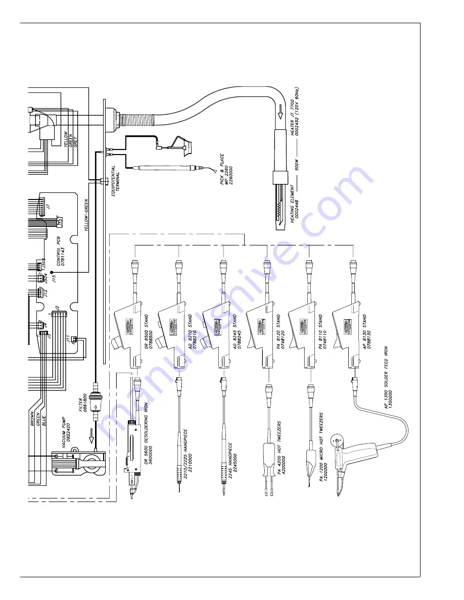
Страница 21: ...20 ELECTRIC WIRING DIAGRAM Valid from serial n 99751 ...

Страница 22: ...21 ...

Страница 23: ...22 ...

Страница 24: ...23 ...

Страница 25: ...24 ...

Страница 26: ...25 ...

Страница 27: ...26 ...

Страница 28: ... 0 669 17 0 669 00 0934030 18 5 0 728 18 5 0 728 Supplied with the station øD D D D D 0932190 0932190 0932190 0932190 0932190 A B mm inches mm inches TRIPOD ø C mm inches 20 0932050 39 1 535 40 0932250 85 3 346 PART Nº 52 0932052 20 0 787 20 0 787 64 0932064 20 0 787 26 1 023 80 0932184 24 0 944 24 0 944 68 0932068 27 1 062 27 1 062 0934020 28 5 1 122 28 5 1 122 00 0934015 31 5 1 240 31 5 1 240 84...

Страница 29: ...productwear due to use or mis use In order for the warranty to be valid equipment must be returned postage paid tothedealerwhereitwaspurchased enclosing this fully filled in sheet DATE OF PURCHASE STAMP OF DEALER SERIAL Nº A MANUFACTURED BY JBC Industrias S A Ramón y Cajal 3 08750 MOLINS DE REI BARCELONA SPAIN Tel 34 93 325 32 00 Fax 34 93 680 49 70 http www jbctools com e mail info jbctools com ...

Отзывы:

Похожие инструкции для AM 6500