background image

- 124 -

UR

 - 323245J

FR

EN

DE

1,70 m


électronique

78

46

143

12
0

75

200

150

40

75

35

188

90

40

30

4xØ5

15

15

73

48

185

60 + 2.5

4.2


électronique

63

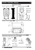
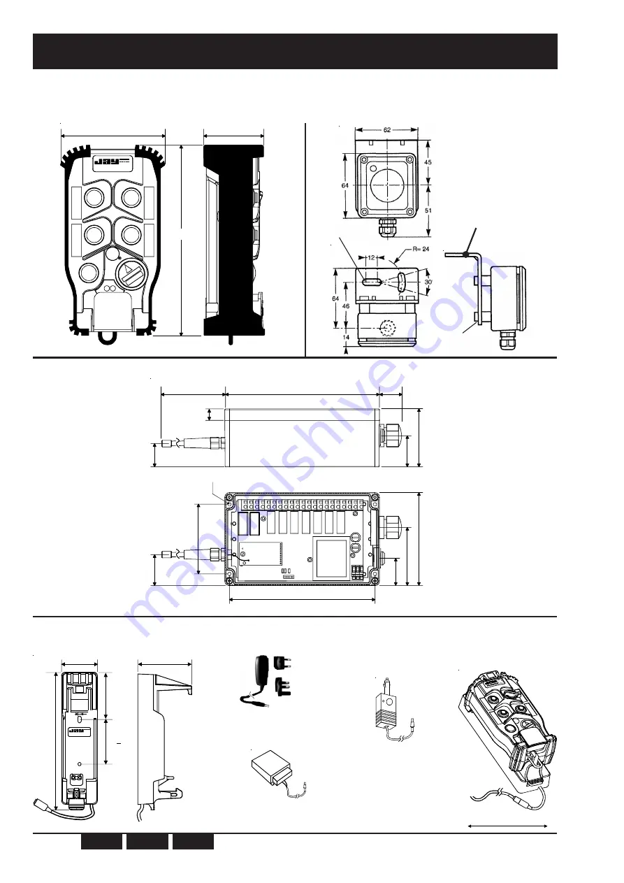
Dimensions / Maße

- Emetteur / Transmitter / Sender 

URE

URE

URE

URE

URE

- Récepteur / Receiver / Empfänger 

URR

URR

URR

URR

URR

- Module IR / IR module / IR-Modul 

UDF

UDF

UDF

UDF

UDF

- Support chargeur industriel/Industrial charger support/Industrielles Ladegerät 

UR

UR

UR

UR

URCi

Ci

Ci

Ci

Ci-B

-B

-B

-B

-B

Adaptateurs/power supply adapter/Spannungsadapter 

U

U

U

U

UC

C

C

C

CC

C

C

C

C•••••

UCCU

UCC1

UCC4

(100-240VAC/5VDC
prises euro. UK/ euro.UK
plugs / Euro.UK Steckern)

(24VDC/5VDC rail DIN /
DIN rail / DIN Schiene)

Ø6

Ø5

- Equerre de fixation

(livrée avec le Module
UDF)

- Mounting bracket

(supplied with module
UDF)

- Befestigungswinkel

(mit UDFgeliefert)

(12-24VDC/6VDC prise
véhicule / vehicle plug /
Fahrzeugsteckdose)

UCC•

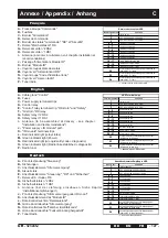
Annexe / Appendix / Anhang

A

Содержание UR Series

Страница 1: ...123 EN Industrielle ultrakompakte Sicherheitsfunkfernsteuerung Technische Notiz und Benutzerhandbuch Seite 83 Anhang Seite 123 DE Notez ici votre numéro de clé électronique numéro à 6 chiffres gravé sur la clé électronique Write your electronic key number here 6 digit number engraved on electronic key Notieren Sie hier die Nummer Ihres elektronischen Schlüssels Nummer mit 6 Ziffern auf den elektro...

Страница 2: ... 2 UR 323245J ...

Страница 3: ...UR 323245J 3 FR EN DE Radiocommande Série UR Notice technique d installation et d utilisation ...

Страница 4: ...16 4 1 5 Clé électronique p 16 4 1 6 Fonction Homme mort arrêt automatique de l émetteur URE p 18 4 2 Récepteur URR p 19 4 2 1 Raccordement aux sorties relais p 20 4 2 2 Caractéristiques des sorties relais p 20 4 2 3 Protection de la carte récepteur et des relais p 21 4 3 Option de démarrage par validation infrarouge p 22 4 3 1 Raccordement électrique du module IR UDF p 22 4 3 2 Positionnement du ...

Страница 5: ...etteur p 34 6 3 4 Validation d une clé électronique p 35 6 3 5 Fonction des voyants de l émetteur URE p 36 6 4 Configuration du récepteur URR p 37 6 4 1 Fonction des voyants du récepteur URR p 37 7 Liste des canaux fréquences disponibles p 38 8 Etiquetage des boutons de fonction de l émetteur p 38 9 Entretien p 40 10 Maintenance p 40 Liste des pièces de rechange de niveau 1 p 40 11 Fonctions spéci...

Страница 6: ...etteur de la radiocommande sur le sol Si cela est indispensable activer l arrêt bouton coup de poing de la télécommande Si plusieurs radiocommandes travaillent sur le même site il convient d utiliser des fréquences radio différentes espacées d au moins 2 canaux par exemple canaux 5 7 9 Plus les canaux choisis sont espacés moins il y aura de risque de perturbation mutuelle En dehors des périodes d ...

Страница 7: ...par l enregistrement du nombre d opérations et de leurs durées pour chaque mouvement option Support chargeur de type industriel pour l émetteur Enfin la maintenance est facilitée Personnalisation entièrement mémorisée dans la clé electronique Logiciel de paramètrage Voyants d aide au diagnostic Ces télécommandes radio intègrent les exigences sécuritaires des normes applicables actuelles et sont co...

Страница 8: ...0 Montbonnot St Martin Ref URR Code Freq 433 050 434 790MHz Date Serie Alim V IP65 Emetteur URE Notice d installation et d utilisation Clé électronique 1 Récepteur URR 2 Etiquette signalétique de l émetteur Etiquette signalétique du récepteur Accessoire de câblage des communs Planches d étiquettes 1 La clé électronique est livrée avec le récepteur 2 Antenne du récepteur à monter à la livraison voi...

Страница 9: ...tion pour la fonction Homme mort et modification de la fréquence radio peuvent être directement effectuées par un opérateur formé et habilité voir modes opératoires au chapitre configuration de l émetteur Différents types de bouton peuvent être utilisés sur l émetteur URE les boutons poussoirs à 1 enfoncement ou simple vitesse BPSV les boutons poussoirs à 2 enfoncements ou double vitesse BPDV les ...

Страница 10: ...uillage B2 B4 lors de l appui simultané sur ces deux boutons seul le bouton B4 est pris en compte face avant de l URE Interverrouillages standards définis dans la référence commerciale du récepteur URR voir 3 2 Pour les cas de correspondances bouton relais non standards veiller à bien remplir la fiche de correspondance se trouvant dans le couvercle de l URR 2 2 Correspondance boutons de fonction r...

Страница 11: ... B Emetteur URE radio bandes 433 434 MHz sans option sans fonction additionnelle ou spéciale Type de boutons en 1ére rangée BPSV BPSV Type de boutons en 2ème rangée COM2 COM2 livré avec 2 planches d étiquettes référencées UWE202 et UWE207 Référence principale Configuration des boutons de fonction Voir tableau des configurations réalisables ci dessous Type de communication et version 2 Radio bandes...

Страница 12: ...dio bandes 433 434 MHz 1 Radio bandes 433 434 MHz option démarrage par IR 1 Tension d alimentation 4 12 24 VDC A 24 48 VAC B 115 230 VAC Fonction additionnelle 0 standard x spécial la définition du matériel a fait l objet d une fiche de personnalisation Correspondance des boutons relais Nombre de relais commandés par les couples de boutons type BPDV 1 3 relais ou pas de BPDV 2 4 relais X spécial l...

Страница 13: ...ique référence URR0C40 B 111 sans option 6 relais de fonction 2 relais de sécurité 1 relais Marche Klaxon alimentation 12 24VDC interverrouillage des boutons n 1 n 2 et n 3 n 4 avec mise à l état repos des relais correspondants bandes 433 434MHz canal 01 livré avec une clé électronique référence URR0CA0 111 sans option 6 relais de fonction 2 relais de sécurité 1 relais Marche Klaxon alimentation 2...

Страница 14: ...e à l antenne réf VUB086 Référence Désignation URWE21 B Clé électronique programmée 1 Important Veuillez spécifier à la commande le numéro de la clé électronique initialement noté en première page de cette notice ou à defaut de ne pas disposer du n de clé Le code d identité du récepteur associé à l émetteur et la configuration des boutons de l émetteur OWR01 Kit prise BNC pour antenne débrochable ...

Страница 15: ...e d accumulateur Lithium Cycles charge décharge 300 cycles minimum sans dégradation de la capacité Temps de charge complète typique 2h30 à 20 C si batterie complètement déchargée Pour une utilisation typique des boutons de fonction 50 H à 50 d utilisation à 20 C 40 H à 50 d utilisation à 20 C Autonomie après une charge de 10 mn lorsque la batterie est déchargée environ 1h d émission disponible 20 ...

Страница 16: ...le par un opérateur formé voir 6 3 la configuration des boutons de fonction montés sur l émetteur et le type de bouton poussoir ou rotatif le masque des boutons fonction spéciale et le registre d options démarrage IR micro vitesse etc Pendant la charge le voyant orange de l émetteur est allumé en continu le voyant vert retranscrit le niveau de charge Voyant vert clignotant charge rapide Voyant ver...

Страница 17: ... nouvel émetteur URE suivre la procédure du 6 3 4 En cas de perte de cette clé électronique Vous pouvez nous commander une autre clé électronique référence URWE21 B en n oubliant pas de spécifier à la commande Le numéro unique à 6 chiffres de l ancienne clé noté au déballage par vos soins sur la première page de cette notice ou à défaut de ne pas disposer de ce numéro Le code d identité du récepte...

Страница 18: ...émetteur sera désactivé au bout de 99 secondes sans utilisation Remise en marche après activation de la fonction Homme mort Appuyer sur le bouton d arrêt coup de poing de l émetteur Déverrouiller le bouton d arrêt coup de poing de l émetteur Attendre l extinction du voyant orange de l émetteur 2 secondes Appuyer sur le bouton vert Marche Klaxon si option démarrage par validation infrarouge présent...

Страница 19: ...ation 20 C à 50 C Poids 1 1 Kg environ Signalisation 1 voyant vert alimentation 1 voyant rouge 1 voyant vert de diagnostic 1 voyant rouge d état par relais Protection de l alimentation contre les inversions de polarités pour versions DC contre les surintensités par fusible Tension d alimentation et consommation max avec les 2 relais de sécurité le relais Klaxon et 6 relais de fonctions enclenchés ...

Страница 20: ... avec une identification des points de connexion par des numéros La section des fil souples utilisable est comprise entre 0 08 mm et 2 5 mm Aucune liaison commune n est réalisée sur les circuits imprimés les contacts sont tous libres de potentiel Un accessoire portant la référence UDWR12 permet de réaliser facilement les communs souhaités livré en standard avec le récepteur Nombre de commutations ...

Страница 21: ...ntée en 230VAC 160 mA 250 VAC T F1 Relais de sécurité Pas de protection Relais Marche Klaxon Pas de protection Relais de fonction Pas de protection Version AC Contre les surintensités 1 fusible sur la phase Protection thermique non réversible du transformateur en cas de surcharge au secondaire Version DC Contre les surintensités 1 fusible sur V Contre les inversions de polarité 1 diode sur V 4 2 3...

Страница 22: ...n 22 à 24 du récepteur URR La liaison peut être allongée jusqu à 2x10m soit 30m au total grâce à l accessoire référencé UDWR10 comprenant un câble blindé et son connecteur Raccordement du module IR au récepteur URR module IR Couleur des fils du module IR voir l annexe B pour l emplacement du bornier de raccordement du module IR En complément du démarrage en mode normal le démarrage par validation ...

Страница 23: ...iocommandes travaillent sur un même site il convient d utiliser des fréquences espacées d au moins deux canaux par exemple 5 7 9 et au besoin un plan de fréquence devra être rédigé en repérant les différents équipements commandés et leur fréquence de travail 5 3 Repérage de l équipement commandé Si plusieurs appareils sont équipés de télécommandes travaillant dans le même voisinage par exemple dan...

Страница 24: ...upe jusqu à la limite intérieure de celui ci 4 Revisser l écrou spirale jusqu au point dur puis effectuer de tour pour bloquer le guide antenne et assurer l étanchéité Vérifier que le guide est bien maintenu S assurer que l antenne est entrée au maximum dans le guide pour permettre une réception optimale Boitier récepteur Ecrou spirale Guide 5 4 Montage de l antenne récepteur URR avant mise en ser...

Страница 25: ...e Si ces conditions ne sont pas respectées il est nécessaire d utiliser une antenne extérieure avec sa rallonge connectique BNC qui peuvent être commandées séparément Pour le récepteur URR l utilisation d une antenne extérieure nécessite l acquisition et l installation du kit antenne BNC débrochable référencé OWR01 voir montage en Annexe Incorrect Correct URR 5 6 Câblage métal métal métal Pour évi...

Страница 26: ...ableau des correspondances livré avec le récepteur étiquette sur le couvercle du boitier et l Annexe B un exemple de câblage est donné en Annexe D pour les ensembles standards Référence récepteur 5 6 1 Câblage du récepteur URR Ne pas effectuer de mouvement de levier sur le tournevis afin d éviter d endommager le bornier et le circuit imprimé de la carte mère du récepteur URR insérer un tournevis v...

Страница 27: ...lectriques pour la commande de puissance par exemple 6 1 Précautions de mise en service L installateur doit impérativement s assurer du répérage de la clé électronique par rapport au récepteur commandé s assurer que le canal radio choisi correspond au plan de fréquence établi sur le site procéder à un contrôle final de la bonne correspondance Bouton Relais souhaitée Lors du contrôle précédent l in...

Страница 28: ...iver de commande noter le temps au bout duquel les relais de sécurité du récepteur retombent et vérifier si cette durée correspond bien à celle livrée en standard 4mn ou spécifiée à la commande programmation spéciale voir fiche de personnalisation ou après changement de celle ci par un opérateur formé et habilité en suivant la procédure décrite au paragraphe 6 3 3 Limites de portée radio et zone d...

Страница 29: ...l URE Relais de sécurité de l URR Voyant vert de l URE Voyant rouge de l UDF si option démarrage IR installée 3 états du voyant orange de l URE état charge batterie Arrêt actif par appuis sur le bouton d arrêt coup de poing OU Dernière action sur un bouton poussoir de fonction 1 Durée de la temporisation Homme mort Arrêt passif batterie déchargée UTILISATION 2 Charge batterie 50 50 Charge batterie...

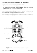
Страница 30: ...é de la clé électronique vers l émetteur Ces opérations de configuration utilisent des procédures mettant en oeuvre les boutons n 1 n 2 arrêt coup de poing et Marche Klaxon sans avoir à ouvrir l émetteur ni le récepteur Par un mode opératoire spécifique le responsable de l équipement peut verrouiller ou déverrouiller l accès à la programmation voir 6 3 1 6 3 Configuration et paramétrage du système...

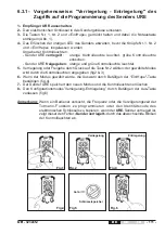
Страница 31: ... non verrouillé voyants orange et vert allumés 5 Sélectionner le verrouillage ou le non verrouillage par appui sur le bouton n 2 le mode sélectionné est répercuté sur l affichage des voyants fig 2 3 6 Valider le mode sélectionné en appuyant sur le bouton Marche Klaxon fig 4 7 L émetteur URE sauvegarde le nouveau mode dans la clé électronique les voyants s éteignent 8 Sortir du mode de configuratio...

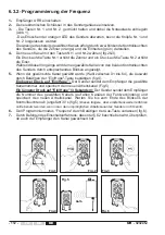
Страница 32: ...e pression sur le bouton n 2 une incrémentation des unités Pendant ces opérations le canal nouvellement sélectionné est affiché par des clignotements des 2 voyants de l émetteur 5 Une fois que le canal désiré est sélectionné choix du n 01 à 64 actionner le bouton Marche klaxon pour valider le choix fig 4 Un appui bref sur marche l émetteur envoie le numéro du canal sélectionné au récepteur et sauv...

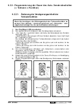
Страница 33: ... l émetteur URE 3 Tout en maintenant le bouton n 1 pressé déverrouiller le bouton d arrêt coup de poing de l émetteur fig 1 Attendre l extinction du voyant orange de l émetteur avant de relâcher le bouton n 1 L affichage du type d unité de comptage pour la fonction homme mort se fait par les deux voyants de l émetteur Si le voyant orange est allumé et le voyant vert éteint l unité de comptage est ...

Страница 34: ...t orange représentant les dizaines de minute ou dizaines de seconde 0 10 20 à 90 et le voyant vert représentant les minutes ou secondes 0 à 9 4 Sélectionner la nouvelle durée avec les boutons n 1 et n 2 fig 2 3 Une pression sur le bouton n 1 entraîne une incrémentation des dizaines et une pression sur le bouton n 2 une incrémentation des unités Pendant ces opérations la durée nouvellement sélectio...

Страница 35: ... clé électronique dans le boitier de l émetteur 3 Tout en maintenant les boutons n 2 et Marche Klaxon pressés déverrouiller le bouton d arrêt coup de poing de l émetteur fig 1 Attendre l extinction du voyant orange de l émetteur avant de relâcher les boutons n 2 et March Klaxon Les 2 voyants de l émetteur URE clignotent rapidement 4 Actionner le bouton marche afin de réaliser la programmation auto...

Страница 36: ...vant marche 5 clignotements 5 clignotements Erreur d arrêt ou de mise en route détectée Veuillez respecter les conditions de mise en route du 6 2 Avant marche 6 clignotements 6 clignotements Erreur d arrêt ou de mise en route détectée Veuillez respecter les conditions de mise en route du 6 2 Avant marche 7 clignotements 7 clignotements Erreur interne clé électronique ou émetteur URE Avant marche 8...

Страница 37: ...Micro sécurité 2 VERT LED Micro sécurité 1 ROUGE Indication de l alimentation Normal Indication de la validité du code d identité Etat du relais de Klaxon marche Tous Donne la qualité de la réception radio Normal LED Power ON VERT LED Klaxon ROUGE Tous LEDs relais de commande ROUGES Tous Etat du relais de fonction N LED relais de sécurité ROUGE Tous Etat des relais de sécurité 6 4 Configuration du...

Страница 38: ...75 1 50 434 325 2 07 433 250 29 433 800 2 51 434 350 2 08 433 275 30 433 825 1 2 52 434 375 2 09 433 300 31 433 850 2 53 434 400 2 10 433 325 32 433 875 1 2 54 434 425 2 11 433 350 33 433 900 2 55 434 450 2 12 433 375 34 433 925 1 2 56 434 475 2 13 433 400 35 433 950 2 57 434 500 2 14 433 425 36 433 975 1 2 58 434 525 2 15 433 450 37 434 000 2 59 434 550 2 16 433 475 38 434 025 1 2 60 434 575 2 17...

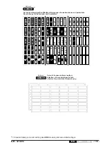
Страница 39: ...N O R D S U D O U E S T E S T L E F T R I G H T 1 2 1 1 2 1 2 3 3 4 3 4 1 2 1 2 1 2 3 GATE ON OFF S H U N T R P M R P M 1 2 1 2 4 7 8 9 4 5 6 2 3 3 4 4 3 3 4 3 UWE207 Référence Kit de 90 étiquettes mouvements fonctions spéciales et personnalisation noir blanc pour commutateurs et boutons poussoirs dont 16 étiquettes pour marquage personnalisé au feutre idélébile Planche d étiquettes livrée en stan...

Страница 40: ...é du récepteur doivent retomber en moins de 2 secondes Entretien de l émetteur URE Cette télécommande requiert un minimum d entretien Vérifier régulièrement le bon état de l émetteur en accordant une attention particulière aux membranes des boutons de fonction et au connecteur de la clé électronique Procéder au nettoyage de l émetteur en éliminant tout corps étranger y adhérant N utiliser que des ...

Страница 41: ...cations ou adjonctions ont été effectuées par le client sans l accord écrit de notre Société La responsabilité de la Société JAY Electronique pendant la période de garantie est limitée à tout vice de matière ou de construction elle comprend la réparation en ses ateliers ou le remplacement gratuit des pièces reconnues défectueuses après expertise de ses services techniques Elle ne peut donner droit...

Страница 42: ... 42 UR 323245J FR EN DE ...

Страница 43: ...UR 323245J 43 FR EN DE UR Series Industrial radio remote control Installation and user technical manual ...

Страница 44: ...f battery charge states p 56 4 1 5 Electronic key p 57 4 1 6 Dead man function Automatic shutdown of transmitter URE p 58 4 2 Receiver URR p 59 4 2 1 Connection to relays p 60 4 2 2 Relay characteristics p 60 4 2 3 Protection of receiver board and relays p 61 4 3 Infrared startup option IR p 62 4 3 1 Electrical connection of IR module UDF p 62 4 3 2 IR module UDF position p 62 5 Installation and r...

Страница 45: ...cation of the duration before transmitter shutdown p 74 6 3 4 Validation of an electronic key p 75 6 3 5 Transmitter URE indicator light functions p 76 6 4 Configuring the receiver URR p 77 6 4 1 Receiver indicator light functions p 77 7 Available frequency channels p 78 8 URE transmitter function button labels p 78 9 Servicing p 80 10 Maintenance p 80 List of LEVEL 1 parts p 80 11 Special functio...

Страница 46: ...ble press the stop palmswitch on the radio control If several radio controls are used on the same site different radio frequencies should be used spaced by at least two channels for example channels 5 7 9 etc The more space there is between the chosen radio channels the less the risks of disturbance are When not in use remove the electronic key Store it in a safe and tracked down place Do not forg...

Страница 47: ...ns controlled Light weight ultra compact transmitter Transmitter endurance and fast charging battery Adaptability to all radio configurations of the environment by possibility for changing frequency by a trained operator Mechanical protection of function buttons to avoid any unintentional action Transmitter carrying strap which hooks onto belt when unit is idle or removable shoulder strap optional...

Страница 48: ...d recommendations IMPORTANT 1 The electronic key is delivered with the receiver 2 The receiver antenna must be assembled following procedure described at Installation and recommendations U P D O W N E V E R S E R O R W A R D F N O R T H S O U T H W E S T E A S T N O R D S U D O U E S T E S T L E F T R I G H T 1 2 1 1 2 1 2 3 3 4 3 4 1 2 1 2 1 2 3 GATE ON OFF S H U N T R P M R P M 1 2 1 2 4 7 8 9 4...

Страница 49: ...ation and Frequency configurations can be directly modified by a trained operator see chapter configuring the UR radio remote control Various types of button can be used on the URE transmitter One step pushbuttons single speed BPSV Two step pushbuttons double speed BPDV Rotary switches with 2 fixed positions COM2 Rotary switches with 3 fixed positions COM3 Rotary switches with 3 positions with aut...

Страница 50: ...program n 3 The 2nd button of the interlocked pair has priority ex B2 B4 interlocked when these two buttons are pressed simultaneously only button B4 is acknowledged URE front panel Standard interlocking configurations defined in sales reference for URR product see 3 2 For non standard button relay configurations be sure to properly fill in the configuration sheet located in the URR cover 2 2 Corr...

Страница 51: ...ronic key is to be ordered separately Example URE2150 B URE radio transmitter 433 434 MHz bands without option without additional or special function type of buttons in 1st row BPSV BPSV type of buttons in 2nd row COM2 COM2 Delivered with 2 label kits ref UWE202 and UWE207 Main reference Function button configuration See table below Type of communication and version 2 Radio 433 434 MHz bands 3 Rad...

Страница 52: ...identity code and the associated transmitter button configuration Main reference 3 additional reference digits Type of communication and version 0 Radio 433 434 MHz bands 1 Radio 433 434 MHz bands option starting up by infrared validation Power supply 4 12 24 VDC A 24 48 VAC B 115 230 VAC 1 This only includes the required programming for the receiver the UDF IR module must be ordered separately Pr...

Страница 53: ...B 111 without option 6 function relays 2 safety relays 1 On Horn relays power supply 12 24VDC button n 1 n 2 and n 3 n 4 interlocked with output relays set to OFF state 433 434MHz canal 01 delivered with an elec key reference URR0CA0 111 without option 6 function relays 2 safety relays 1 On Horn relays power supply 24 48VAC button n 1 n 2 and n 3 n 4 interlocked with output relays set to OFF state...

Страница 54: ...ct connection to antenna ref VUB086 Reference Description URWE21 B Programmed electronic key 1 Important Be sure to specify the following on order Electronic key number 6 digit number written on cover page or if you do not have the key number the associated receiver identity code and transmitter button configuration OWR01 BNC plug kit for plug in deported antenna 2 see installation in Appendices V...

Страница 55: ...43 mm 1 orange LED Battery low and Diagnostic 1 green LED ON Battery charging and Diagnostic Range will vary according to environment conditions of transmitter and reception antenna metal frameworks walls Dimensions Housing Attachment when idle Weight with battery Storage temperature range Charging temperature range Endurance Radio Operating temperature range Battery Caution charging outside this ...

Страница 56: ...pecial function and the option register IR start up micro speed etc 4 1 3 Charging the battery Transmitter URE support charger URCi B power supply adapter UCC To recharge a transmitter Do not remove the electronic key from the transmitter Stop the transmitter by pressing its stop plamswitch button 1 Install the transmitter on the support charger the power supply adapter UCC must be connected to th...

Страница 57: ... in the procedure in 6 3 4 If your electronic key is lost You can order another electronic key reference URWE21 B making sure to specify the following information on the order The unique 6 digit number of the old key written on the cover page of this manual when you unpacked your product or if you do not have the key number the associated receiver identity code on receiver descriptive label and tr...

Страница 58: ...the transmitter will be deactivated after 99 seconds if no action has been performed on the transmitter Restarting the transmitter after the Dead man function has been activated Press the stop palmswitch button on the transmitter Unlock the stop palmswitch button on the transmitter Press the green On Horn button If option starting up by IR validation chosen the operator has to aim at the infrared ...

Страница 59: ... Storage temperature range 30 to 70 C Operating temperature range 20 C to 50 C Weight 1 1 Kg approx Indicator light 1 green LED Power ON 1 red LED 1 green LED for diagnostic 1 red LED per relay Protection of power supply Against polarity inversions for DC versions Against overcurrents by fuse Power supply and maximum consumption with 2 safety relays 1 Horn relay and 6 function relays activated Out...

Страница 60: ... selection control 6 2 1 T contact Summary table of relays available on receiver 4 2 2 Relay characteristics 4 2 1 Connection to relays Connections are made on spring terminals with connection points identified by numbers The flexible wire section without end fitting is between 0 08 mm square and 2 5 mm square No common line is provided on the printed circuits all contacts are potential free An ac...

Страница 61: ...5VAC 315 mA 250 VAC T F2 Board supplied with 230VAC 160 mA 250 VAC T F1 Safety relays No protection On Horn relay No protection function relays No protection AC version Against overcurrents 1 fuse on phase Non reversible thermal protection of transformer in the event of overloads at secondary DC version Against overcurrents 1 fuse on V Against polarity inversions 1 diode on V 4 2 3 Protection of r...

Страница 62: ...ior to activating the safety and function relays 1st condition Radio reception of a startup request message sent by the URE transmitter to the URR receiver 2nd condition Infrared reception of the same startup of message simultaneously sent by the URE to the URR via the UDF IR module The IR transmission takes place when the On Horn pushbutton is pressed Following this startup procedure only recepti...

Страница 63: ... same site frequencies spaced by at least two channels for example 5 7 9 should be used and if necessary a frequency plan should be drawn up specifying the various machines controlled and their working frequency 5 3 Movement control arrows If there are several equipment fitted with similar radio remote control systems working in the same neighbourhood e g in a plant each transmitter shall carry a ...

Страница 64: ... the cable gland base upto the limit in the base 4 Tighten the spiral nut to the sticking point then add a quarter turn to lock the antenna guide and ensure tightness of the assembly Check that the guide is securely mounted Check that the antenna entered at most the guide to allow an optimal reception Receiver housing Spiral nut Guide 5 4 Installation of receiver antenna before comissioning Antenn...

Страница 65: ... points The antenna must never cross through a wall not even an insulating wall If the above requirements cannot be observed an external antenna must be used with extension BNC connection External antenna and extension must be ordered separately For the URR receiver use of an external antenna requires that the user purchases and installs the plug inantennakit reference OWR01 see installation in Ap...

Страница 66: ... Vertically insert the screwdriver flat tip screwdriver of 1 5 to 3 mm width in the slot located opposite the wire Insert the wire Remove the screwdriver If flexible stranded wire is used crimped terminations should be used to avoid false contacts and short circuits To open the connection terminal strips 5 6 2 Wiring the electrical power supply of receiver URR See Annexe B for location of power su...

Страница 67: ...in electrical cabinet for power control for example 6 1 Precautions when commissioning The installer must ensure that the transmitter and receiver identity and radio channel match correctly ensure that the radio channel chosen corresponds to the frequency plan set up for the site perform a final check to verify that the desired Button Relay correspondence is in place During the previous check the ...

Страница 68: ...er safety relays are deenergized and check that this duration corresponds to the standard duration supplied 4min or the duration specified on order special programming see customisation sheet or to the new duration defined by a trained and authorized operator in accordance with the procedure described in 6 3 3 IR start up option If the IR start up mode is used evaluate the limit of its area of act...

Страница 69: ... function pushbuton Passive shutdown when Dead man duration is exceeded 1 or Battery is disconnected discharged 2 or Electronic key removed from URE in operation Active shutdown by pressing stop palmswitch button OR 4 states of URE 1 Dead man duration Battery charge 50 10 URR safety relays URE green indicator light Red indicator light of UDF if IR start up option installed 3 states of orange indic...

Страница 70: ...smitter memory These configuration operations use procedures implementing buttons n 1 n 2 stop plamswitch and On Horn without having to open the transmitter or the receiver By a specific operating mode the person in charge of the equipment can lock or unlock the access to the programming see 6 3 1 électronique n 1 n 2 n 3 n 4 See next pages for configuration procedures Stop plamswitch button Progr...

Страница 71: ... Indicator lights statuses transmitter locked orange indicator light on green indicator light off transmitter unlocked orange and green indicator lights on 5 Select locked or unlocked by pressing button n 2 the selected mode is shown by the indicator lights fig 2 3 6 Validate the selected mode by pressing the On Horn button fig 4 7 The transmitter saves the new mode in the electronic key and switc...

Страница 72: ... n 2 to increment the units During these operations the newly selected channel is displayed by the 2 indicator lights on the transmitter which flash accordingly 5 Once the desired channel is selected between 01 and 64 press the On Horn button to validate your selection fig 4 Briefly pressing On the transmitter sends the selected channel number to the receiver and saves its new working channel fig ...

Страница 73: ...ssing button n 2 the selected unit is shown by the indicator lights 5 Once the desired unit is selected press the On Horn button to validate your selection fig 4 6 Exit the programming mode by pressing the stop palmswitch button fig 6 6 3 3 Procedure for programming the automatic shutdown function of the transmitter Dead man function 6 3 3 1 Modification of the time unit used by the Dead man funct...

Страница 74: ...ns n 1 and n 2 fig 2 3 Press button n 1 to increment the tens and button n 2 to increment the units During these operations the new time selected is displayed by the two indicator lights on the transmitter 5 Once you have selected the desired dead man time between 01 and 99 press the On Horn button to validate your selection fig 4 Caution No 99 corresponds to an infinite dead man time when the cou...

Страница 75: ...tronic key or the original transmitter 1 Switch off the receiver 2 Insert the electronic key in the transmitter unit 3 Hold buttons n 2 and On Horn pressed while unlocking the stop palmswitch button fig 1 Wait until the orange indicator goes off before releasing buttons n 2 and On Horn The 2 indicator lights on the transmitter URE will flash rapidly 4 Press the On Horn button to perform automatic ...

Страница 76: ...shes 4 times Faulty button s Before On Horn bt Pressed Flashes 5 times Flashes 5 times Stop or start up error detected Be sure to observe start up conditions specified in 6 2 Before On Horn bt Pressed Flashes 6 times Flashes 6 times Stop or start up error detected Be sure to observe start up conditions specified in 6 2 Before On Horn bt Pressed Flashes 7 times Flashes 7 times Internal error electr...

Страница 77: ...y state OFF OFF Relay state ON ON Safety micro 2 LED GREEN Safety micro 1 LED RED Indicates power supply state Normal Indicates validity of identity code State of horn relay ON All Indicates radio reception quality Normal LED Power ON GREEN Horn LED RED All Function relays LEDs RED All State of function relay N Safety relay LED RED All Indicates safety relay state 6 4 Configuring the URR receiver ...

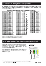
Страница 78: ...4 675 2 21 433 600 43 434 150 2 22 433 625 1 44 434 175 2 433 434MHz band with adjacent channel intervals of 0 025MHz The various button functions are identified by means of adhesive labels placed in he recesses provided in the transmitter unit envelope at each button location The labels are supplied in the form of sheets with the various labels you will need for your application Simply choose the...

Страница 79: ...48 white blank labels customization 48 transparent protecting labels UWE205 Reference U P D O W N E V E R S E R O R W A R D F N O R T H S O U T H W E S T E A S T N O R D S U D O U E S T E S T L E F T R I G H T 1 2 1 1 2 1 2 3 3 4 3 4 1 2 1 2 1 2 3 GATE ON OFF S H U N T R P M R P M 1 2 1 2 4 7 8 9 4 5 6 2 3 3 4 4 3 3 4 3 UWE207 Reference Label sheets provided as standard supply with URE transmitter...

Страница 80: ... from the transmitter the receiver safety relays should de energise within 2 seconds Rerence Description PR0248 Battery Lithium for transmitter URE PR0231 Mechanical part of the industrial charger this part can be used as wall support for URE transmitter or can be used to repair the URCi industrial charger Reference Description PR0123 Fuse kit URE transmitter URR receiver List of parts which can b...

Страница 81: ...ditions to the equipment performed by the customer without written approval by JAYElectronique The JAY Electronique responsability during the warranty period is limited to material and construction defects This warranty comprises repair in the JAY workshops or replacement free of charge of parts recognized to be defective following expert inspection by the Jay Technical Department The warranty sha...

Страница 82: ... 82 UR 323245J FR EN DE ...

Страница 83: ...UR 323245J 83 FR EN DE Funkfernsteuerung Serie UR Technische Notiz und Benutzerhandbuch ...

Страница 84: ...üssel s 96 4 1 6 Totmann Funktion Automatisches Abschalten des Senders s 98 4 2 Empfänger URR s 99 4 2 1 Relaisanschluß s 100 4 2 2 Eigenschaften der Relais s 100 4 2 3 Schutz der Empfängerkarte und der Relais s 101 4 3 Option Startfreigabe durch Infrarot IR s 102 4 3 1 Anschluß des Infrarotmoduls s 102 4 3 2 Stellung des IR Moduls UDF s 102 5 Installation und Empfehlungen s 103 5 1 Entstörung s 1...

Страница 85: ...erkennung eines elektronischen Schlüssels s 115 6 3 5 Funktion der Kontrolleuchten des Senders URE s 116 6 4 Konfiguration des Empfängers URR s 117 6 4 1 Funktion der Kontrolleuchten des Empfängers s 117 7 Liste der verfügbaren Frequenzen s 118 8 Etikettierung der Funktionstasten des Senders s 118 9 Pflege s 120 10 Wartung s 120 Liste der Ersatzteile Niveau 1 s 120 11 Sonderfunktionen s 121 12 Gar...

Страница 86: ...assen Sollte dies unbedingt erforderlich sein dieAbschalttaste aus Taste der Funkfernsteuerung betätigen Wenn mehrere Funkfernsteuerungen am gleichen Ort eingesetzt werden muß auf unterschiedlichen Funkfrequenzen gesendet werden die mindestens 2 Kanäle auseinander liegen zum Beispiel Kanäle 05 07 09 Je weiter die gewählten Kanäle von einander entfernt sind um so geringer ist das Störungsrisiko Aus...

Страница 87: ...auf eine bestimmte Zone zu beschränken und die Identität zu bestätigen des Arbeitsteams Speicherung der Benutzung der Funkfernsteuerung durch Speicherung der Arbeitsschrittanzahl und der Dauer jeder Bewegung Option Industrieller Halter mit integriertem Ladegerät für den Sender Zubehör Und nicht zuletzt Bedienerfreundliche Wartung Individualisierung komplett im elektronischen Schlüssel gespeichert ...

Страница 88: ...34 790MHz Date Serie Alim V IP65 Sender URE Technische Notiz elektronischer Schlüssel 1 Empfänger URR 2 Batterieladegerät Produkterkennungsschild des Senders Gemeinsames Kabelzubehör Etikettenblätter 1 Der elektronische Schlüssel ist mit dem Empfänger geliefert 2 Empfängerantenne bei der Lieferung einzubauen Siehe Kapitel Installationsempfehlungen électronique Spannungsadapter für den Batterielade...

Страница 89: ... wird verriegelt geliefert die dem elektronischen Schlüssel entsprechenden Konfigurationen Totmann Dauer und Frequenz können direkt von einem geschulten Bediener geändert werden siehe Betriebsweisen im Kapitel Senderkonfiguration Mit dem URE Sender können folgende Tasten genutzt werden 1 Gang Drucktaste BPSV 2 Gänge Drucktaste BPDV Drehschalter mit 2 festen Stellungen COM2 Drehschalter mit 3 feste...

Страница 90: ...eordnet Diese beiden Relais können sich entweder in OFF oder in ON Stellung befinden wenn sich der Schalter in der Mittelstellung befindet Diese Angaben sind in der Artikelreferenz des Produkts URR aufgeführt Siehe Kapitel Identifizierung der Produkte Bei jeder gewünschten Zwischenverriegelung löst die gleichzeitige Betätigung der beiden Tasten eine von drei durch die Programmierung festgelegte Be...

Страница 91: ...ronische Schlüssel muss separat bestellt werden Beispiel URE2150 B Sender URE Funk Bereich 433 434MHz ohne Option ohne Zusatz oder Spezialfunktion Art der Tasten in der 1 Reihe BPSV BPSV Art der Tasten in der 2 Reihe COM2 COM2 mit 2 Etikettenblätter ref UWE202 und UWE207 geliefert Hauptreferenz Tastenkonfiguration Siehe mögliche Konfigurationen in nachstehender Tabelle Typ der Kommunikation und ve...

Страница 92: ...rsion 0 Funk Bereich 433 434 MHz 1 Funk Bereich 433 434 MHz Option Starten durch IR 1 Versorgungsspannung 4 12 24 VDC A 24 48 VAC B 115 230 VAC Zusätzliche oder Spezialfunktion 0 standard x Spezial die Definition des Materials wurde auf einem gesonderten Blatt aufgezeichnet Programmierung der Zwischenverriegelung der Drucktasten vom Typ BPSV oder BPDV Nr 1 Nr 2 und Nr 3 Nr 4 0 Keine Zwischenverrie...

Страница 93: ...enz URR0C40 B 111 ohne Option 6 Relais 2 Sicherheitsrelais 1 Hupe Relais Versorgungsspannung 12 24VDC Zwischenverriegelung der Drucktasten n 1 n 2 und n 3 n 4 mit Deaktivierung der Ausgangsrelais Bereich 433 434MHz Kanal Nr 01 mit electronischen Schlüssel Referenz URR0CA0 111 ohne Option 6 Relais 2 Sicherheitsrelais 1 Hupe Relais Versorgungsspannung 24 48VAC Zwischenverriegelung der Drucktasten n ...

Страница 94: ...R Referenz Bezeichnung URWE21 B Programmierter elektronischer Schlüssel 1 Wichtig Bitte geben Sie bei der Bestellung folgendes an die Nummer des elektronischen Schlüssels Nummer mit 6 Ziffern auf dem Deckblatt notiert oder wenn man nicht über die Schlüsselnummer verfügt den Identitätscode des dem Sender zugeordneten Empfängers und die Tastenkonfiguration des Senders OWR01 Satz BNC Tuner Steckverbi...

Страница 95: ...ose Ein Batterie wird geladen Diagnose Die Reichweite variiert je nach den Umgebungbedingungen des Senders und der Empfängerantenne Dachstühle Metallwände etc Umgebungstemperatur Signalisation Dimensionen 1 orange Kontrolleuchte 1 grüne Kontrolleuchte Gehäuse Befestigung in Ruhestellung Gewicht mit Batterie Lagertemperatur Ladetemperatur Autonomie Funk Batterie Achtung Langsames Aufladen außerhalb...

Страница 96: ...nd Tastenart Drucktaste oder Drehschalter Tastendeaktivierung Sonderfunktionen Optionsverzeichnis Infrarot Start Mikrogang etc 4 1 3 Aufladen der Batterie Sender URE Ladehalterung URCi B Zum Aufladen der Batterie Den elektronischen Schlüssel nicht vom Sender herausnehmen Den Sender beim Drücken auf die Notaustaste ausschalten 1 Den Sender auf die Ladehalterung setzen der Spannungsadapter UCC muss ...

Страница 97: ...der URE programmiert werden Siehe Programmierverfahren unter 6 3 4 Bei Verlust des elektronischen Schlüssels Sie können einen neuen elektronischen Schlüssel bestellen Artikelnummer URWE21 B unter Angabe von folgenden Informationen bei der Bestellung 6stellige Nummer des alten Schlüssels den Sie beim Auspacken auf dem Deckblatt dieser Notiz vermerkt haben oder wenn Sie nicht über diese Nummer verfü...

Страница 98: ...drückt wird und der Wert N 99 Sekunden beträgt wird der Sender nach 99 Sekunden Nichtbenutzung deaktiviert Wiederinbetriebnahme nach Aktivierung der Totmann Funktion Auf die Notaustaste des Senders drücken Die Notaustaste des Senders lösen Appuyer sur le bouton vert Marche Klaxon wenn die Option Startfreigabe per Infrarot vorhanden ist muss der Bediener auf das UDF Infrarotmodul zielen Verzögerung...

Страница 99: ... bis 30 550 mA 24VDC 20 bis 20 430 mA AC 24VAC 15 bis 10 1 A 48VAC 15 bis 10 475 mA 115VAC 15 bis 10 200 mA 230VAC 15 bis 10 90 mA Passive Abschaltung 1 15 s max Aktive Abschaltung 0 16 s max Beim Starten 0 50 s max Beim Steuern 0 07 s max Kabelausgang Strom oder IR Module 1 Kunststoffstopfen PG M16 für Kabel Ø 5 bis 7 mm 1 Steuerausgänge 1 Kunststoff PG Verschraubung M25 für Kabel Ø 14 bis 20 mm ...

Страница 100: ...n bei 24VDC 8A 10 000 000 Umschaltungen bei 12VDC 10mA min Strömung Versuche nach EN 60947 5 1 DC13 bei 24V 0 5A AC15 bei 230V 2A Relaisfunktion Relaisanzahl Anzahl der Anschlußpunkte pro Relais Sicherheit 2 2 1 NO Kontakt Befehl Ein Hupe 1 2 1 NO Kontakt Befehl Bewegung oder Auswahl 6 2 1 NO Kontakt Tabelle zur Übersicht über die verfügbaren Empfängerrelais 4 2 2 Eigenschaften der Relais 4 2 1 Re...

Страница 101: ... Karte 315 mA 250 VAC T F2 Mit 230VAC gespeiste Karte 160 mA 250 VAC T F1 Sicherheitsrelais Kein Schutz Ein Hupe Kein Schutz Bewegung oder Auswahl Kein Schutz Eigenschaften der Sicherungen Version AC Gegen Überspannungen 1 Sicherung auf der Phase Nicht umkehrbarer Wärmeschutz des Trafos bei Überlastung der Sekundärspule Version DC Gegen Überspannung 1 Sicherung auf V Gegen Polumkehrungen 1 Diode a...

Страница 102: ...frarotübertragung erfolgt während der Betätigung der Ein Hupe Taste Nach dieser Startphase ist für den Betrieb nur der Empfang der Funkmeldungen erforderlich Zusätzlich zum Starten im Normalmodus erfolgt das Starten mit Infrarot durch das Halten des Senders vom Bediener auf den Infrarotempfänger der sich unter der zu steuernden Ausrüstung befindet 23 22 24 Weiß Blau Schwarz Anschluss des IR Moduls...

Страница 103: ...en die mindestens zwei Kanäle auseinander liegen z B 5 7 9 Gegebenfalls muss ein Frequenzplan aufgestellt werden auf dem die einzelnen gesteuerten Ausrüstungen und deren Betriebsfrequenz aufgeführt werden 5 3 Hilfestellung bei der Steuerung von Bewegungen Wenn mehrere Hebevorrichtungen mit hängender Last mit Funkfernsteuerungen ausgerüstet sind und in unmittelbarer Nachbarschaft arbeiten z B in ei...

Страница 104: ...n 4 Die Spiralmutter wieder bis zum Anschlag festziehen und anschliessend eine Drehung durchführen um die Antennenführung zu blockiren und die Dichtigkeit zu gewährleisten Sicherstellen daß die Führung ordnungsgemäss gehalten wird Sicherstellen daß die Antennendraht in die Führung höchstens eingetreten ist um einen optimalen Empfang zu erlauben Empfängergehäuse Spiralmutter Führung 5 4 Einbau der ...

Страница 105: ...abgeschirmten Orten aufgestellt werden Metallschrank Mauer aus Stahlbeton Metalldach oder wand usw Jegliches Hindernis zwischen Sender und Antenne verringert die Reichweite Soweit wie möglich muss die Antenne von Kabeln der Klasse 3 und Leistungselementen entfernt sein Stromversorgung Motoren Drehzahlregler und sich dabei in einer für den Funkempfang günstigen Zone befinden und für den Anschluss d...

Страница 106: ...st Empfängerreferenz 5 6 1 Verkabelung des Empfängers URR 5 6 2 Verkabelung der elektronischen Stromversorgung des Empfängers URR Keine Hebelbewegung auf den Schraubenzieher ausüben um Beschädigungen der Klemmleiste und der gedruckten Schaltung der Grundkarte des Empfängers URR zu vermeiden einen Schraubenzieher vertikal mit flacher Klinge von 1 5 bis 3 mm Breite in den Schlitz gegenüber dem Kabel...

Страница 107: ...chtsmaßnahmen bei der Inbetriebnahme Der Installateur muss unbedingt sicherstellen dass der Identitätscode des elektronischen Schlüssels mit dem des Empfängers übereinstimmt sicherstellen dass die Funkfrequenz des Senders mit der des Empfängers identisch ist überprüfen ob der gewählte Funkkanal dem für den Standort aufgestellten Frequenzplan entspricht eine Endkontrolle der gewünschten Tasten Rela...

Страница 108: ... aufschreiben nach welchem Zeitraum die Sicherheitsrelais des Empfängers umspringen und überprüfen ob dieser Zeitraum dem Standardzeitraum 4 min oder dem bei der Bestellung angegebenen Zeitraum Spezialprogrammierung siehe Sonderblatt oder der durch einen geschulten und befugten Bediener durch Befolgen des unter 6 3 3 beschriebenen Verfahrens erfolgten Änderung entspricht Grenzen der Funkreichweite...

Страница 109: ...ngen URE Leuchte Batteriezustand Passive Abschaltung bei entladener Batterie 1 Dauer der Totmann Verzögerung Entriegelung der roten Notaustaste Einschalten des URE Druck auf die grüne Taste Ein Hupe BETRIEB Letzte Betätigung einer Funktionsdrucktaste Passive Abschaltung wenn Totmann Dauer überschritten 1 oder Batterie abgetrennt entladen 2 oder Bei eingeschaltetem URE abgezogener elektronischer Sc...

Страница 110: ...it Minuten Standard oder 0 bis 99 Sekunden außer Standard ist Übertragung des Identitätscodes des elektronischen Schlüssels auf den Sender Bei den Verfahren zur Ausführung dieser Schritte werden die Tasten Nr 1 Nr 2 Notaus und Ein Hupe benutzt Sender und Empfänger müssen nicht geöffnet werden Durch ein besonderes Betriebsverfahren kann der Teamleiter den Zugang zur Programmierung verriegeln oder e...

Страница 111: ...e erloschen Sender URE freigegeben orange und grüne Kontrolleuchte leuchtet 5 Verriegelung oder Freigabe durch Druck auf die Taste Nr 2 wählen der gewählte Modus wird durch die Kontrolleuchten angegeben fig2 3 6 Wenn der Modus gewählt wurde die Auswahl durch Betätigen der Ein Hupe Taste bestätigen fig 4 7 Der Sender URE speichert den neuen Modus und die Kontrolleuchten erlöschen 8 Den Konfiguratio...

Страница 112: ... Während dieser Vorgänge wird der neugewählte Kanal von den beiden Kontrollleuchten des Senders durch entsprechendes Blinken angezeigt 5 Wenn der gewünschte Kanal gewählt wurde Wahl zwischen 01 bis 64 die Auswahl durch Betätigen der Ein Hupe Taste bestätigen fig 4 Ein kurzer Druck auf Ein Hupe Der Sender sendet dem Empfänger die gewählte Kanalnummer und speichert den neuen Arbeitskanal Fig 5 Ein l...

Страница 113: ...rfolgt durch die beiden Kontrollleuchten des Senders Wenn die orange Led leuchtet und die grüne Led nicht leuchtet ist die Einheit Minuten Wenn die orange Led nicht leuchtet und die grüne Led leuchtet ist die Einheit Sekunden 4 Um vom Einheitentyp Minuten auf Sekunden umzuschalten oder umgekehrt auf die Taste Nr 2 drücken Während dieses Vorgangs wird die gewählte Einheit anhand der beiden Kontroll...

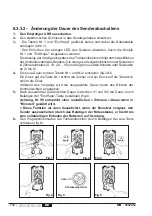
Страница 114: ...s Senders Die orange Led zeigt die Minuten oder Sekunden in Zehnereinheiten 0 10 20 90 und die grüne Led die Minuten oder Sekunden an 0 bis 9 4 Die neue Dauer mit den Tasten Nr 1 und Nr 2 einstellen fig 2 3 Ein Druck auf die Taste Nr 1 erhöht die Zehner und ein Druck auf die Taste Nr 2 erhöht die Einer Während des Vorgangs wird die neugewählte Dauer durch das Blinken der Kontrolleuchten angegeben ...

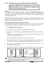
Страница 115: ...nger URR ausschalten 2 Den elektronischen Schlüssel in das Sendergehäuse einsetzen 3 Die Tasten Nr 2 und Ein Hupe gedrückt halten und dabei die Notaustaste entriegeln Abb 1 Das Erlöschen der orangen LED des Senders abwarten bevor die Knöpfe Nr 2 und Ein Hupe losgelassen werden Die beiden Kontrollleuchten des Senders URE blinken schnell 4 Die Ein Taste drücken um die automatische Programmierung des...

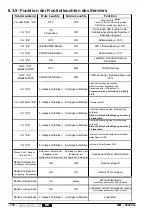
Страница 116: ...es Aufblinken Fehler Abschaltung oder Einschaltung entdeckt Bitte die Einschaltbedingungen unter 6 2 beachten Vor Ein 6 maliges Aufblinken 6 maliges Aufblinken Fehler Abschaltung oder Einschaltung entdeckt Bitte die Einschaltbedingungen unter 6 2 beachten Vor Ein 7 maliges Aufblinken 7 maliges Aufblinken Interner Fehler elektronischer Schlüssel oder Sender URE Vor Ein 8 maliges Aufblinken 8 malige...

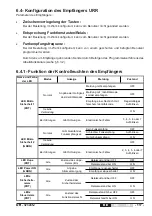
Страница 117: ...Sicherheit 1 ROT LED Mikro Sicherheit 2 GRÜN Normal Angabe der Gültigkeit des Identitätscodes Zustand des Funktionsrelais N LEDs Steuerrelais ROT Alle Alle LED Hupe ROT LEDs Sicherheits relais ROT Alle Zustand der Sicherheitsrelais LED Power ON GRÜN Zustand des Hupe Relais Ein Alle Angabe Stromversorgung Gibt Qualität des Funkempfangs an Normal 6 4 Konfiguration des Empfängers URR Parameter des Em...

Страница 118: ...5 2 11 433 350 33 433 900 2 55 434 450 2 12 433 375 34 433 925 1 2 56 434 475 2 13 433 400 35 433 950 2 57 434 500 2 14 433 425 36 433 975 1 2 58 434 525 2 15 433 450 37 434 000 2 59 434 550 2 16 433 475 38 434 025 1 2 60 434 575 2 17 433 500 39 434 050 2 61 434 600 2 18 433 525 40 434 075 2 62 434 625 2 19 433 550 41 434 100 2 63 434 650 2 20 433 575 1 42 434 125 2 64 434 675 2 21 433 600 43 434 ...

Страница 119: ...S T L E F T R I G H T 1 2 1 1 2 1 2 3 3 4 3 4 1 2 1 2 1 2 3 GATE ON OFF S H U N T R P M R P M 1 2 1 2 4 7 8 9 4 5 6 2 3 3 4 4 3 3 4 3 UWE205 Referenz Set mit 48 unbeschrifteten weißen Etiketten 48 durchsichtigen Schutz etiketten für persönliche Kennzeichnung UWE207 Referenz Set mit 90 schwarz weißen Etiketten Bewegungen Sonderfunktionen und persönliche Beschriftung für Stellschalter und Drucktaste...

Страница 120: ... Antennendichtigkeit Wenn das Zubehör OWR01 externer Antennenstecker BNC siehe installation im Anhang benutzt wird Anschluss der Antenne prüfen und Antenne auf Sauberkeit und Oxidation prüfen Zum Überprüfen der aktiven Abschaltung drückt man die Notaustaste Die Sicherheitsrelais des Empfängers müssen sofort umspringen Zum Überprüfen der passiven Abschaltung den elektronischen Schlüssel vom Sender ...

Страница 121: ...tung durch einen unserer Technischen Dienste Die Garantie schließt keinen Anspruch auf Schadensersatz ein Im Streitfall in Bezug auf ein Ersatzteil oder die Bezahlung ist der Gerichtsstand nach unserer Wahl das Handelsgericht Grenoble TRIBUNAL DE COMMERCE DE GRENOBLE ebenso im Berufungsfall oder bei Mehrzahl von Beklagten Deaktivierung einiger Funktionstasten durch den elektronischen Schlüssel And...

Страница 122: ... 122 UR 323245J FR EN DE ...

Страница 123: ...UR 323245J 123 FR EN DE Annexes Appendix Anhang ...

Страница 124: ...eur industriel Industrial charger support Industrielles Ladegerät UR UR UR UR URCi Ci Ci Ci Ci B B B B B Adaptateurs power supply adapter Spannungsadapter U U U U UC C C C CC C C C C UCCU UCC1 UCC4 100 240VAC 5VDC priseseuro UK euro UK plugs Euro UKSteckern 24VDC 5VDC rail DIN DIN rail DIN Schiene Ø6 Ø5 Equerre de fixation livrée avec le Module UDF Mounting bracket supplied with module UDF Befesti...

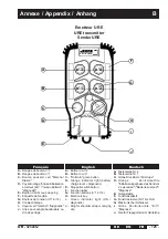
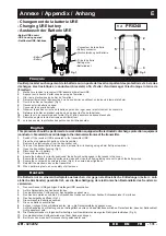
Страница 125: ...e Français English Deutsch A Button row n 2 B Button row n 1 C On Horn green button D Orange indicator light battery charge level diagnostic E Stop palmswitch button F Function label G Function buttons n 1 à n 4 H Electronic key i Green indicator light ON diagnostic J Ring for shoulder strap or carrying clip A Tastenreihe Nr 2 B Tastenreihe Nr 1 C Grüne Drucktaste Ein Hupe D Orange Kontrolleuchte ...

Страница 126: ...23245J FR EN DE RS2 RS1 RK F1 F2 R1 R2 R3 R4 R5 R6 22 23 24 1 2 3 4 5 6 7 8 9 10 11 12 13 14 15 16 17 18 19 20 21 A J C K D F G H i O N M L B E P Récepteur URR URR receiver Empfänger URR Annexe Appendix Anhang C ...

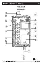
Страница 127: ...Radio tuner A PG Verschraubung Steuerung B Sicherungen C Anschlussklemmen Stromversorgung D Steuerrelais E Anschlussklemmen Steuerung RK und Sicherheit F Relais Ein Hupe RK G Sicherheitsrelais n 2 RS2 H Sicherheitsrelais n 1 RS1 i Antenne bei der Lieferung einzubauen Siehe Kapitel Installationsempfehlungen J PG Verschraubung Stromversorgung oder IR modul K Anschlussklemmen des Moduls IR L Rote Kon...

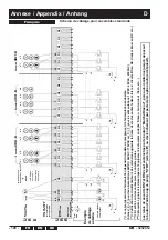
Страница 128: ...m URR R5 R6 R5 7 6 5 4 7 6 5 4 R6 Ensemble UR31 B Ensemble UR21 B Schéma de câblage pour ensembles standards Le raccordement de l alimentation dépend du modèle de récepteur et de l alimentation souhaitée bornes 2 1 pour les alimentations 24VDC 24VAC 115VAC ou 3 1 pour les alimentations 12VDC 48VAC 230VAC L utilisation de circuits limiteurs de surtension augmente la durée de vie des contacts des re...

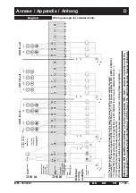
Страница 129: ...5 14 13 12 11 10 9 8 URR pow supply R5 R6 R5 7 6 5 4 7 6 5 4 R6 UR31 B unit UR21 B unit The power supply connection depends on the type of receiver and the power supply required terminals 2 1 for power supplies 24VDC 24VAC 115VAC or 3 1 for power supplies 12VDC 48VAC 230VAC Relay life is increased by the use of surge limiters ex RC network for AC Zener diodes for DC etc K1 and K2 contactors must h...

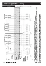
Страница 130: ...Notausknopfs stop aktive Abschaltung beibehalten oder Auslösen durch Sendeverlust passives Abschalten R1 RS1 RS2 RK R2 R3 R4 R5 R6 STOP Nr 1 Nr 2 Nr 3 Nr 4 U R R Pack URC41 B U L Ua Fa N Fb K1 K2 K2 K1 U R E Ein Hupe K2 K1 R1 R2 R3 R4 Nr 1 Nr 2 Nr 3 Nr 4 K2 K1 Nr 1 Nr 2 K2 K1 R1 R2 R3 R4 U L N Fb U L N Fb U L N Fb 1 21 20 19 18 17 16 15 14 13 12 11 10 9 8 7 6 5 4 15 14 13 12 11 10 9 8 15 14 13 12 ...

Страница 131: ... housing using a 5mm flat tip screwdriver 5 Open the transmitter housing Fig 1 6 Disconnect the old battery 7 Connect the new battery 8 Ensure the battery is correctly positioned the battery should engage in the recess in the cover 9 Ensure the seal and its bearing surface are clean and close the housing taking care not to pinch the battery wires 10 Secure the covers with its screws in order Fig 2...

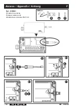
Страница 132: ...t antenne externe External antenna kit Abnehmbare Antenne BNC Kit OWR01 A B C électronique S2 S1 S2 S1 K RS2 RS1 RK RS2 RS1 RK R1 R2 R3 R4 R5 R6 22 23 24 1 2 3 4 5 6 7 8 9 10 11 12 13 14 15 16 17 18 19 20 21 A B C Annexe Appendix Anhang F ...

Страница 133: ...laration de conformité CE Emetteur URE Declaration of conformity CE Transmitter URE Konformitätserklärung CE Funksender URE Available in English at Verfügbar auf deutscher Sprache www jay electronique com Annexe Appendix Anhang G ...

Страница 134: ...éclaration de conformité CE Récepteur URR Declaration of conformity CE Receiver URR Konformitätserklärung CE Empfänger URR Available in English at Verfügbar auf deutscher Sprache www jay electronique com Annexe Appendix Anhang G ...

Страница 135: ...assistance Helfen Sie uns bei der Verbesserung des Installations und Benutzerhandbuchs Informations personnelles Personal information Persönliche Angaben Merci de nous faire parvenir cette page par courrier ou par fax à l adresse suivante Please send us this form completed either by post or by fax at Bitte schicken Sie uns diese Seite per Fax oder per Post an folgende Adresse JAY Electronique Serv...

Страница 136: ... 136 UR 323245J ...

Страница 137: ...UR 323245J 137 NOTES ...

Страница 138: ... 138 UR 323245J NOTES ...

Страница 139: ...UR 323245J 139 ...

Страница 140: ...Realisation JAY 323245J FR EN DE PMD 15 07 15 E D d A ZAC la Bâtie rue Champrond F38334 SAINT ISMIER cedex 33 0 4 76 41 44 00 33 0 4 76 41 44 44 www jay electronique com électronique ...

Отзывы: