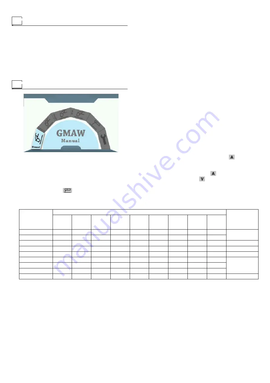
WARNING: Before welding, check that the data on the
power
source plate correspond to the supply voltage and
frequency.
• Start up the welder by turning the switch on the back panel
to 1 (
N.B.:
the machine will display the last settings made
before it was switched off when it is turned on again);
• Set the various units according to the chosen welding
process.
Figure 13
ELECTRODE WELDING (MMA)
For coated electrode welding with devices that can be
adjusted from the user’s “Arc Force” and “Hot Start”.
You can access this welding mode by adjusting the EN-
CODER knob to MMA
and then pressing the EN-
CODER key.
Connect up the welding cables following description in para-
graph “Connecting up welding - ELECTRODE welding ca-
bles”.
Welding parameters
Table 3 s
hows the values of current to use with the respec-
tive electrodes for the welding of common steels and
low-grade alloys. These data have no absolute value and
are indicative data only. For a precise choice follow the in-
structions provided by the electrode manufacturer. The cur-
rent to be used depends on the welding positions and the
type of joint, and it increases according to the thickness and
dimensions of the part.
A fairly approximate indication of the average current to use
in the welding of electrodes for ordinary steel is given by the
following formula:
I = 50 × (Øe - 1 )
where:
I = intensity of the welding current Øe = electrode diameter
Example: for electrode diameter 4 mm
I = 50 × (4 -1 ) = 50 × 3 = 150A
The preset values of the welding current
(adjustable
with ENCODER knob) and open-circuit voltage will be dis-
played on the screen before welding starts.
The values of the welding current
being used for weld-
ing and the welding voltage
will appear on the displays
during the welding process.
Table 3
Special functions
NOTE: Press the More parameters key to access more pa-
rameters page.
A brief description of parameters that could
be changed follows
•
Hot start
-
i.e. overcurrent being supplied when the arc is
switched on. (
Hot start
- from 0 to 10 with an adjustment
interval at 1).
•
Arc force
- In
tensive arc drive force to prevent to be
stuck.
•
Anti-stick
- The switch of prevention to stick.
•
VRD
-
The switch of voltage reduction safeguard.
MIG-MAG, MIG PULSED AND MIG DUAL PULSED WELD-
ING
The following jobs must be done before starting to weld:
•
Open the gas cylinder valve slowly and adjust the pressure
regulator to obtain about 1,3 - 1,7 bar;
•
Work the gas check key and adjust the flow to between 14
and 20 l/min. according to the current being used for
welding;
•
The welding machine is now ready to be used.
Manual welding mode (activated for MIG-MAG welding
process only)
Ø ELECTRODE
(mm)
ELECTRODE TYPE - Current adjustment field (A)
WELDING
THICKNESS
(mm)
6010
6011
6012
6013
6020
6027
7014
7015
7016
7018
7024
7028
1,6
-
20-40
20-40
-
-
-
-
-
-
≤ 5
2
-
25-60
25-60
-
-
-
-
-
-
2,4
40-80
35-85
45-90
-
-
80-125
65-110
70-100
100-145
≤ 6,5
3,2
75-125
80-140
80-130
100-150 125-185 110-160 100-150 115-165 140-190
> 3,5
4
110-170 110-190
105-180 130-190 160-240 150-210 140-200 150-220 180-250
> 6,5
4,8
140-215 140-240
150-230 175-250 210-300 200-275 180-255 200-275 230-305
> 9,5
5,6
170-250 200-320
310-300 225-310 250-350 260-340 240-320 260-340 275-365
6,4
210-320 250-400
250-350 275-375 300-420 330-415 300-390 315-400 335-430
8
275-425 300-500
320-430 340-450 375-475 390-500 375-475 375-470 400-525
> 13
Before welding
Welding procedures


