background image

Jason International, Inc.  •  


501.771.4477  


Page 8 of 26


Customer Service :  800.255.5766 

Copyright © 2014 Jason International, Inc.

INSTALLATION INSTRUCTIONS (cont.)

reMOTe MOunTIng Of aIr BlOwer

The Jason AirMasseur

®

 system has been factory installed 

following E.T.L. guidelines. During installation, if remote 
mounting of the blower and its control box is desired, follow 
these procedures.

Note: Do not remote mount the blower and control box more 
than 15 feet [457 cm] away from the air inlet of the bath. 
Choose a location as close as possible to the bath to assure 
maximum efficiency.

1.  Determine layout. The installer is to determine the layout 

of the piping, exact remote mount location, and service 
access before beginning any work. 

a.  Use 1.5" [38 mm] ABS or PVC plastic tubing. 

b.  Locate the control box with the blower in an area 

accessible for servicing. 

c.  To ensure proper functioning of the system, avoid 

remote mounting in a location which requires more 
than six (6) piping direction changes. A 90° direction 
change should be made up of two 45° elbows for 
maximum efficiency.

2.  Install the blower and control box in the remote 

location.

a.  A minimum ventilation opening of 2" x 4" 


[5 cm x 10 cm] for the blower is required, and should 
be designed to draw in indoor ambient air at a mini-
mum of 72°F (22°C).

b.  Attach the blower mount firmly to the floor. 

c.  Attach the piping to the blower’s check valve. Use 

screws to attach the pipe to the check valve and route 
the hose to the remote blower tubing floor cutout 
location. 


CAUTION: Do NOT use ABS or PVC glue near  


the blower, it could ignite and cause a fire.

3.  Attach hose. Attach one end of the blower hose to the 

bath connection with the included clamp.

4.  Pipe stub out. Extend piping stub-out through the floor 

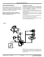
as illustrated in Figure 9. Piping between the remote 
blower location and the bath can be insulated using a 
minimum of 1/2" [12 mm] thick insulation.

 WARNING: Any modification to the equipment is not 

recommended and will VOID THE MANUFACTURER'S 
WARRANTY.

5.  Attach hose.  Attach the other end of the hose to the 

1-1/2" [38 mm] PVC pipe that is plumbed to the blower 
with the included clamp. 

6.  Route cables. Route the keypad cable, low water level/

temperature sensor cable (if applicable), and the light 
cable through the floor cutout to be connected to the 
control box.

WARNING: When routing cables, do not allow the 
cable to be pinched under the bath shell. 

Use the tie buttons attached to the bath to support the 
cables. 

Note: A minimum of 4 feet [122 cm] of hose and cable 
must be free from binding to allow for pulling the 
cables back up through the floor cutout. 

During installation if it is preferred to run the blower 
hose on top of the floor, a 2 1/2" [6.35 cm] diameter 
hole can be drilled at the bottom of the skirt. A means 
to cover the hole, hose, and wires is not provided. 


See Figure 9.

7.  Return to the bath installation section to finish installation 

of the freestanding bath.

Содержание AC553PS

Страница 1: ...e carrier to respond should be reported to the seller and carrier Always file a freight claim promptly The installer is responsible for insuring that the unit is free from defects or shipping damage In the event of a problem DO NOT install the unit If the carton shows sign of damage inspect the product before accepting and describe the problem on the Bill of Lading Jason International is not respo...

Страница 2: ... with the AEC Equipment Cabinet set the AEC carton aside to be installed later 4 Cardboard bath well protector Each bath is provided with a cardboard bath well protector that should be kept in the unit throughout the bathroom construction process Note Overflow drains fill spouts and valves must be installed according to the instructions herein 5 Installation template An installation template is pr...

Страница 3: ...floor Use the four existing 3 8 holes located in the bottom four corners of the skirt to mark where to drill the pilot holes for the four locating studs If installing on a wooden floor 1 4 6mm holes are required and a 5 16 nut to install the locating studs into the wooden floor When installing on a cement slab 3 8 9 5mm holes are required See Figure 3 After marking the hole locations remove the sk...

Страница 4: ...OUNTING OF AIR BLOWER section of this manual before proceeding to the next step 20 Reattach the skirt to the bath by positioning the skirt on the bath and fastening the 5 16 nut and washers to the 5 16 leveling bolts nuts and washers attached to the bath Be sure that the skirt is positioned correctly allowing the PS skirt clips to rest against the back of the skirt 21 Position the bath and skirt a...

Страница 5: ...ce from the GFCI to the bath control shouldbedirectandnotinterruptedbyaswitch Never use a switch in conjunction with a control device This will VOID THE MANUFACTURER S WARRANTY 2 GROUNDING IS REQUIRED The unit should be installed by a qualified service representative and properly grounded 3 INSTALL SERVICE CONNECTION AT LEAST 6 15cm ABOVE SUB FLOOR ALL LOCAL AND STATE ELECTRICAL AND PLUMBING CODES...

Страница 6: ...rical Service AirMasseur Control Box Export The blower control box must be plugged into a dedicated 240V 15A 50 or 60 Hz GFCI protected circuit See Figure 9 Control Box Light Cable Check Valve Blower Blower Mount Keypad Cable Ground Green Wire Neutral White Wire Hot Black Wire Dedicated 120V 50 or 60 Hz GFCI Protected Service L2 L1 GROUND DEDICATED 240V 50 or 60 Hz GFCI PROTECTED SERVICE NOTE USE ...

Страница 7: ...dicated 120V 20A 60Hz GFCI protected circuit See Figure 10 INSTALLATION INSTRUCTIONS cont 240V Electrical Service MicroSilk Control Box The MicroSilk control must be plugged into a dedicated 240V 15A 60Hz GFCI protected circuit See Figure 10 DANGER Do not alter the factory installed wiring All building materials and wiring should be routed away from the equipment or other heat producing components...

Страница 8: ...o the blower s check valve Use screws to attach the pipe to the check valve and route the hose to the remote blower tubing floor cutout location CAUTION Do NOT use ABS or PVC glue near the blower it could ignite and cause a fire 3 Attach hose Attach one end of the blower hose to the bath connection with the included clamp 4 Pipe stub out Extend piping stub out through the floor as illustrated in F...

Страница 9: ...t aside Use the 4 included 12 screws to attach the frame to the floor See Figure 13 ACRYLIC EQUIPMENT CABINET INSTALLATION The Jason Acrylic Equipment Cabinet AEC can be used to house the bath equipment that cannot be remote mounted away from the bath The cabinet is standard on freestanding MicroSilk baths and is available as an op tion for freestanding AirMasseur baths To install the AEC follow t...

Страница 10: ... the appropriate barb using the clamp provided Assure the line will allow proper drainage to the bath fitting The hose must have a continuous drop from the barb to the fitting See Figure 14c Figure 14b Figure 14c 6 Refer to faucet manufacturer s installation instruc tions if a faucet is intended to be mounted on the top of the cabinet and position the plumbing stub outs inside the cabinet Caution ...

Страница 11: ...tic Polish No 2 available from the Jason Dealer It is always preferable to protect the acrylic surface during installation to minimize cleanup and prevent surface damage WATER TESTING Before finishing the installation it is recommended that the bath be water tested and the plumbing tested for leaks 1 Before water testing the bath make sure all plumbing connections are tight DO NOT OVERTIGHTEN 2 Fi...

Страница 12: ...3 Keypad B A To Dedicated 120V 60Hz 15A GFCI Protected Service C Control Box NOTE This diagram also applies to 50 Hz 240V controls and power supply systems Except that the Blower junction box must be connected into one dedicated 240V 15 amp GFCI circuit The AirMasseur Control Box The blower and keypad must be plugged into the proper receptacles for correct operation of the AirMasseur system See Fi...

Страница 13: ...s and power supply systems Except that the Blower junction box must be connected into one dedicated 240V 15 amp GFCI circuit Blower D C Ozone IMC 213 LEDs Keypad B A To Dedicated 120V 60Hz 15A GFCI Protected Service C D Control Box The AirMasseur Control Box The blower keypad LED light and Ozone Sanitation Unit must be plugged into the proper receptacles for correct operation of the AirMasseur sys...

Страница 14: ...ater Temp Sensor Remote E Control Box The AirMasseur Control Box The blower keypad LED light Ozone Sanitation Unit and Water Level Temperature Sensor must be plugged into the proper receptacles for correct operation of the AirMasseur system See Figure 17 for connections A The power cord for the AirMasseur control box must be connected into the proper GFCI dedicated circuit for the system see note ...

Страница 15: ...er supply systems Except that the MicroSilk Pump junction boxes must be connected into one dedicated 240V 20 amp GFCI circuit IMC 263 To Dedicated 120V 60Hz 20A GFCI Protected Service MS Standard 2014 A B C C MS Pump Keypad Control Box INSTALLATION INSTRUCTIONS cont The MicroSilk Control Box The MicroSilk unit and keypad must be plugged into the proper receptacles for correct operation of the Micr...

Страница 16: ...ps controls and power supply systems Except that the MicroSilk Pump junction boxes must be connected into one dedicated 240V 20 amp GFCI circuit Figure 19 IMC 263 MS Premier 2014 A To Dedicated 120V 60Hz 20A GFCI Protected Service C C D D B Ozone MS Pump LEDs Keypad Control Box The MicroSilk Control Box The MicroSilk unit keypad LED light and Ozone Sanita tion Unit must be plugged into the proper ...

Страница 17: ...13 E Water Temp Sensor Remote The MicroSilk Control Box The MicroSilk unit keypad LED light Ozone Sanitation Unit and Water Level Temperature Sensor must be plugged into the proper receptacles for correct operation of the MicroSilk system See Figure 20 for connections A The power cord for the MicroSilk control box must be connected into the proper GFCI dedicated circuit for the system see note B T...

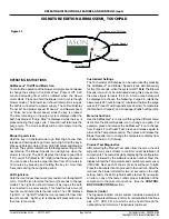
Страница 18: ...ny time the blower is powered a digital control with LCD display window low water and temperature sensors and a 20 minute timer Signature Touchpad Amaincontroltouchpadmountedonthebathdeckfeaturesa LCDreadoutwhichalternatelyindicatesthewatertemperature 5 F and time remaining The Signature Edition touchpad allows the bather to control the blower pump LED mood light and optional jetted neck pillow A ...

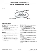
Страница 19: ...ss than two 2 seconds to turn the lights Off or On Hold the icon for more than two 2 seconds to change modes This function has a two 2 hour timer and remembers the last mode OPERATING INSTRUCTIONS FEATURES AND CONTROLS cont OPERATING INSTRUCTIONS AirMasseur On Off Icon The AirMasseur icon is used to activate the blower and the 20 minute timer Pressing the Icon once starts the blower in the Con sta...

Страница 20: ...des a waterproof floatingUniversalRemoteControl Itcontrolsallbathfunctions plus a TV DVD CD etc which can be heard through the optional Sound Immersion Transducers optional AirMasseur On Off Mode Blower Speeds LED Light IR for Remote OPERATING INSTRUCTIONS FEATURES AND CONTROLS cont OPERATING INSTRUCTIONS AirMasseur On Off and Mode Icon Tocontroltheoperationoftheblower simplypressandrelease to cha...

Страница 21: ... timer Press the icon the first time to start the MicroSilk unit Press the icon again to shut off the MicroSilk unit Figure 23 LED Light Icon The LED Light icon is used to operate an LED light if installed Press the icon for less than two 2 seconds to turn the lights Off or On Hold the icon for more than two 2 seconds to change modes This function has a two 2 hour timer and remembers the last mode...

Страница 22: ...enu will be displayed to choose the following Product Test Diagnostics Temperature F or C and Language English or Spanish Menu Instructions Use the top Diagnostic Function icon to scroll through the different menu items Use the bottom Diagnostic Function icon to change an option For example press and release the top icon to change from Product Test to the Temperature option Press and release the b...

Страница 23: ...on i e glass cleaner and a soft wet cloth or sponge Do not run the hydrotherapy system with foaming cleaners or soaps Rinse the bath thoroughly after cleaning USER MAINTENANCE INSTRUCTIONS SURFACE MAINTENANCE Areas with minor scratches or dull surfaces can be restored by applying commercially available plastic polish i e Novus Plastic Polish No 2 available at your Jason dealer followed by an appli...

Страница 24: ...ry Blower shuts off by itself or before time elapses a Blower motor overheated and thermal protection device deactivated motor possibly low voltage a Check that blower has sufficient ventilation and that the intake into the blower is not blocked Clear and allow the motor to cool down Check service wire size b GFCI tripped b Refer to installer dealer Circuit breaker trips repeatedly a Defective bre...

Страница 25: ... control is defective If voltage is pres ent motor is defective b Make sure plug is fully inserted into the outlet Pump operates but no Micro bubbles are injected into water a Venturi clogged b Float valve not operating a Refer to installer dealer b Refer to installer dealer Pump operates but water is not being pumped a Suction or discharge blocked b Suction air leak System usually surges a Remove...

Страница 26: ...onstrictors vasodilators hypnotics narcotics or tranquilizers F Persons with a medical history of heart disease low or high blood pressure circulatory system problems or diabetes should consult a physician before using a therapy bath G Persons using medication should consult a physician before using a therapy bath since some medication may induce drowsiness while other medication may affect heart ...

Отзывы: