Jasic TIG200 Скачать руководство пользователя страница 6

5

Installation

6. When control the welding machine with foot switch, the two-cores and three-cores plugs of foot switch

should be connected with the two-cores and three-cores sockets on the control panel of the welding

machine.

7. Connect the power cord with voltage-matched distribution chamber according to the input voltage grade of

welding machine. The connected voltage must be correct. The power voltage should varies in a permitted

range at the same time.

The welding machine can be operated after finishing the above installation operations.

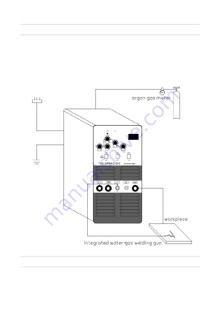
Sketch map for installation of AC.DC TIG-200 model

Installation

Application of AC argon arc welding

1.Locate the “AC/DC transfer switch” at “AC” position.
2.Turn on the power switch and the fan inside the machine start rotating.

Содержание TIG200

Страница 1: ...S MANUAL MODEL AC DC TIG 200 AC DC TIG 250 AC DC TIG 315 INVERTER SERIES Read first please Thank you In order to protect you and others please read this manual and understand it completely before ope...

Страница 2: ...ctive clothing welding protective mask and glass filter Avoid doing harm to lookers on by using appropriate mask or curtain Fire hazard Make sure there is no tinder near operating position because the...

Страница 3: ...he following advantages lower price high applicability for power system The most advantage of this machine is that it adopts double inverting technology and generates a clear square wave Its output ca...

Страница 4: ...0 2 0 2 0 2 Duty ratio 20 80 20 80 20 80 Down slope time S 0 5 0 5 0 5 Post gas S 2 10 2 10 2 10 Remote control Non available Available Available Arc initiation High frequency High frequency High freq...

Страница 5: ...invert in positive and negative direction circularly when take a argon arc welding operation It is positive current time when current flows from tungsten needle to workpiece and it is suitable for wel...

Страница 6: ...n chamber according to the input voltage grade of welding machine The connected voltage must be correct The power voltage should varies in a permitted range at the same time The welding machine can be...

Страница 7: ...ual requirement 1 The current is controlled by knob on the control panel when the transfer switch locates at OFF position 2 The current is controlled by foot switch when the transfer switch locates at...

Страница 8: ...ne which should be dry if the state above occurs and insulation state should be checked with megohmmeter insulation status of connected nodes as well as connected nodes and casing The welding machine...

Страница 9: ...g machine may be damaged if the power voltage exceeds allowable value and take corresponding precautionary measures 4 The back of every welding machine is attached a grounding screw marking a sign of...

Страница 10: ...network connected with input cable and assure it is available 3 Check input cable and find out any short circuit Power indicator lights but fan does not rotate or stops after several rotations and no...

Страница 11: ...cator does not light 2 If the abnormal indicator does not light a The transformer on middle board may be damaged pls check the primary inductance and Q value with bridge circuit b The double times rec...

Страница 12: ...the machine and unplug the power terminal of high frequency arc starting power supply near the VH 07 inserter and restart the machine i Individual MOFSET on MOS board is damaged if the abnormal indica...

Отзывы: