page 8 of 8
MODEL 424
PRODUCTS CORPORATION
33 ANDERSON ROAD, MIDDLETOWN, CONNECTICUT 06457-4926
UNITED STATES OF AMERICA E--MAIL.
TEL. 860-347-7271 FAX. 860-347-6978 WWW.
jarvisproducts.com
JARVIS
®
6205001
4.2 Loosen the blade holding set screw (item 46)
about one half turn.
4.3 Reinsert the hex key in the hole at the outer end
of the blade and pull the blade out.
5 BLADE INSTALLATION:
5.1
STANDARD BLADE SUPPORT (End Cutting):
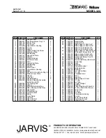
a. Align blade (item 43) with blade support
(item 42).
The blade should extend approx-
imately three inches from the end of the
blade support.
b. Slide the blade onto the blade support until
the crimp in the blade is touching the end of
the blade support.
c. Use a rubber hammer and tap the end of the
blade towards the body of the saw until the
crimp in the blade slides into the slot in the
blade support.
d. Tighten the set screw (item 46) with the hex
key (item 58).
5.2
HEAVY DUTY BLADE SUPPORT (Heavy Duty):
a. Place the slotted end of blade (item 45) into
the guide in the blade support (item 44).
b. Slide the blade over the blade support to-
wards the body of the saw.
Make sure that
the tabs on the blade extend over each side
of the blade support.
5.3 Slide the blade into the rod and stud assembly
(item 48) as far as it will go.
5.4 Tighten the set screw (item 46) with the hex key
(item 58).
6 BLADE SUPPORT REMOVAL:
6.1 Remove cap nuts (items 36).
6.2 Remove blade support (item 42 or 44), threaded
stud (item 56) and bushings (item 53).
7 BLADE SUPPORT INSTALLATION:
7.1 Reverse steps 6.1 -- 6.2.
8 GENERAL DISASSEMBLY:
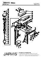
8.1 Remove blade (item 43 or 45) and blade support
(item 42 or 44).
8.2 Remove handle cover (item 73).
8.3 Pull air conveying components (items 60--72)
out of saw housing (item 38).
8.4 Disassemble individual components as neces-
sary.
8.5 Examine o--rings (item 67), screen (item 70) and
valve seat (item 66). Replace parts, if necessary.
8.6 Remove bottom cover plate (item 23) and gas-
ket (item 24).
8.7 Insert a small block of wood between the con-
necting link (item 27) and the saw housing (item
38) to stop the rotation of the connecting link.
Remove lock nuts (item 25).
8.8 Remove connecting link (item 27); gear stud nut
(item 37); gear, bearing and stud assembly (item
30) and drive stud (item 49).
8.9 Remove set screw (item 46), clamp ring (item
47) and rod and stud assembly (items 48 and 49)
from end of saw housing (item 38).
8.10 Remove and examine seals (item 50) and bush-
ing (item 51).
8.11 Clean the gear housing cavity to remove any
contaminated lubricant.
8.12 Remove screws (item 2) and top cover (item 4).
8.13 Remove elbow (item 34) and long nipple (item
35) from lower motor housing (item 20).
8.14 Remove items 5--20 from saw housing (item
38).
8.15 Unthread pinion gear (item 19) from spindle
(item 18).
8.16 Disaasemble further as necessary to inspect part
for wear. Replace parts as required.
8.17 Reassemble by reversing these steps.
maintenance instructions


