JAR Systems MD-51 SP Series Скачать руководство пользователя страница 3

  3 

For Additional Support Call: 866.393.4202 or Email: [email protected] 
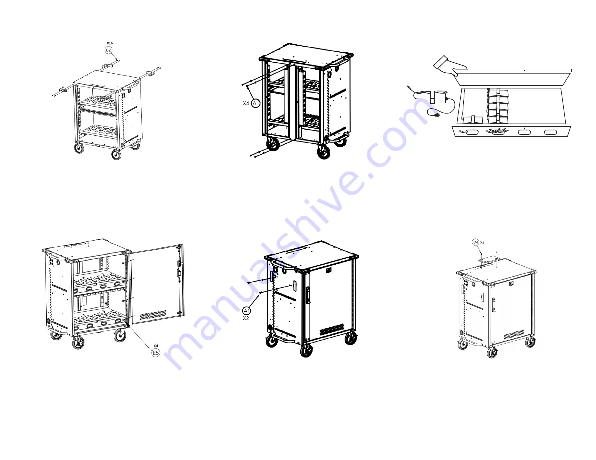
6:

   Attach the gray rubber bumpers to each corner of the 

cart’s top using 4 screws (B2) on each. The bumpers 
have a top and bottom side to them. The side with 
the mold marks should be facing down. To allow for 
the cart to be squared in a later step, 

do not fully 

tighten the screws during this step.

7:

   Attach the rear center support to the top and bottom 

panels of the cart using 2 screws with 2 washers (A1) 
on each end. To allow for the cart to be squared in a 
later step, 

do not fully tighten the screws during 

this step. 

8: OPTIONAL-

 If installing the charging cables at the 

same time as the cart assembly, installing after step 
7 provides the most unimpeded workflow. 

See page 

6 for cable management instructions

Don’t worry, 

you can still easily install the charging cables after the 
cart is fully assembled if needed.

9:

  Attach the door to the hinge on the right side panel 

with 4 screws and 4 washers (E5). Insert the Torx key 
(F6) through one of the screw holes on the hinge and 
door to help hold it in place. Remove the key once the 
first 3 screws are inserted. Insert the 4th screw while 
holding the door. Check that the door is square and 
opens/closes without striking the frame.

10:

  Attach the brackets for wrapping the power cable 

to the cart’s left side panel using 1 screw and washer 
(A1) on each.

11:

  Attach the mounting plate for the Intelligent Charging 

System to the top of the cart using 2 screws with 
washers (D4).

Содержание MD-51 SP Series

Страница 1: ...nt Service Plus Carts MD 51XX SP Assembly and Configuration Manual Version D For a copy of the most up to date manual please contact a JAR Systems representative or visit www JAR Systems com Support M...

Страница 2: ...screws and 3 washers A1 in each corner 2 Install the tray lid for the bottom shelf using one screw and one washer A1 on each side 3 Install the upper tray Position over the studs in the side panels an...

Страница 3: ...the same time as the cart assembly installing after step 7 provides the most unimpeded workflow See page 6 for cable management instructions Don t worry you can still easily install the charging cabl...

Страница 4: ...not use a power tool as it will leave scratches on the cable cover 16 Check the cart square by placing a rafter square in the bottom corner of the door frame or use the door as a guide Check that the...

Страница 5: ...Secure each tray lid shut with one short screw with a silver washer A1 22 Insert the metal device dividers into the trays See page 8 for instructions on inserting the dividers 21 MD 5150 Model Only L...

Страница 6: ...est method of arranging the cables that come with your device figures D E F below Use of cable clips G7 H8 is optional for any configuration 2 Determine the length of cable that is needed to reach fro...

Страница 7: ...dled at all twist ties or Velcro ties may be helpful If the devices have particularly large AC adapters approximately 5 x 2 x 1 25 the adapters will fit more snugly in the tray In this case it may be...

Страница 8: ...every slot in the tray will have a divider in it and there may be extra unused dividers at the end of the assembly process depending on which hole pattern is used Use the guides below to determine wh...

Отзывы: