


32
Mechanical adjustment
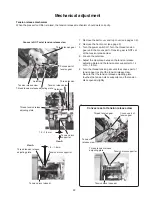
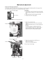
Presser foot lifter stopper position (2)
Supporter spring
Setscrew H
Setscrew I
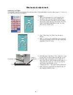
6. Remove the supporter spring.
Remove the setscrews H and I.
Remove the front bracket.
Front bracket
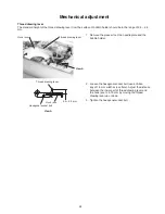
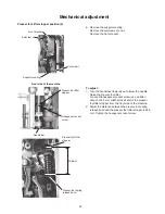
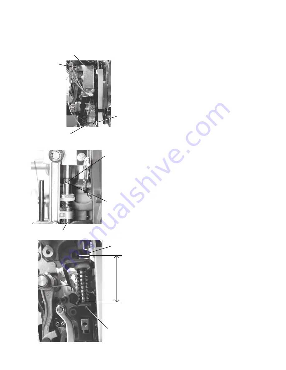
39.6 mm
Presser foot lifter
stopper
To adjust:
1. Turn the handwheel toward you to lower the needle.
Raise the presser foot lifter.
Loosen the hexagonal socket screw (use an Allen
wrench of 2.5 mm width across flats) of the presser
foot lifter stopper from the front side of the machine.
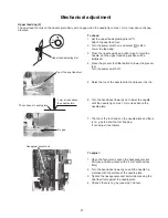
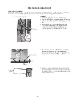
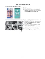
2. Adjust the distance between the presser foot spring
release base and the presser foot lifter stopper to 39.6
mm. Tighten the hexagonal socket screw.
Front side of the machine
Needle bar
Hexagonal socket
screw
Presser foot lifter
stopper
Presser foot spring
release base


