


22
Setscrew
Thread tension gear
Tension discs supporter
Thread tension release
adjusting plate
Tension discs (closed)
Convex part of
tension gear
Tension release claw
Tension release claw
Setscrew
Thread tension
1.2 – 1.8 mm
View A
1.2 – 1.8 mm
Thread tension release
adjusting plate
Tension discs
supporter
View A
Tension
release claw
Tension discs supporter
Thread tension release
adjusting plate
Tension discs (opened)
Thread tension release adjusting plate
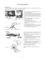
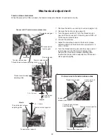
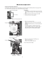
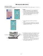
Mechanical adjustment
Tension release mechanism
When the presser foot lifter is raised, the tension release mechanism should work correctly.
1. Remove the belt cover and top cover (see pages 1-2).
2. Remove the front cover (see page 5).
3. Turn the power switch off. Turn the thread tension
gear until the convex part of tension gear is NOT set
at the tension release claw.
4. Loosen the setscrew.
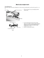
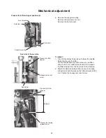
5. Adjust the clearance between the tension release
adjusting plate and the tension disc supporter to 1.2
mm – 1.8 mm.
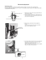
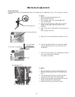
6. Turn the thread tension gear until the convex part of
tension gear is set at the tension release claw.
Be sure that the tension release adjusting plate
touches the tension discs supporter and the tension
discs opened slightly.
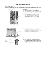
Convex is NOT set at tension release claw
Convex is set at tension release claw
Convex part of
tension gear
Thread tension gear


