


33
Setscrews TP
Needle plate sensor
Fig. 1
Needle plate base plate
Slide plate positioning plate
Fixed cutter spacer
◎
mark
11–11.5 mm
Rear side of
the needle
plate
Needle plate sensor knob
Needle plate
Micro switch
Actuator
Micro switch base
plate
Setscrews TP
Fig. 2
Fig. 3
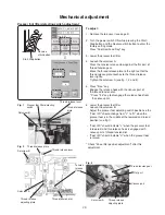
Mechanical adjustment
Needle plate sensor
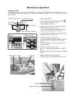
To remove:
1. Remove the belt cover, top cover, base cover, bed
cover, free-arm cover and the front cover (see pages
1 to 4 and 6).
2. Disconnect the connector from the needle plate
sensor switch from the printed circuit board A (see
page 8).
3. Remove the setscrews TP and the needle plate sensor
.
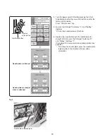
To attach:
1. Attach the needle plate sensor switch with the
setscrews TP. Tighten the setscrews TP lightly.
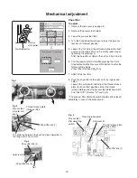
2. Connect the needle plate sensor switch connector to
the printed circuit board A.
3. Check the needle plate sensor and adjust as
necessary (see the adjustment procedure below).
4. Tighten the setscrews TP firmly.
5. Attach the front cover, free-arm cover, bed cover, base
cover, top cover and the belt cover.
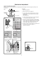
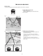
To check and adjust:
1. Prepare the needle plate and the needle plate for
straight stitch.
2. Insert the needle plate base plate under the fixed
cutter spacer and the slide plate positioning plate.
Press the
◎
mark to attach the needle plate.
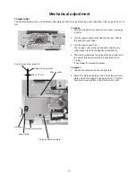
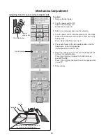
3. The distance between the bottom side of the needle
plate and the micro switch base plate should be in the
range of 11 to 11.5 mm.
If not, loosen the setscrews TP and move the base
plate up or down to adjust it. Tighten the setscrews TP
firmly after the adjustment.
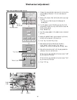
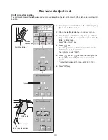
The actuator of the micro switch should be alighed
with the needle plate sensor knob as shown in fig 3.
Содержание MC9900
Страница 1: ...SERVICE MANUAL PARTS LIST MC9900...


