PNP
- No current flowing from B to E = Current allowed to flow from C to E
- Current flowing from B to E = No flow from C to E
B-base E-emitter C-collector
To place transistor on the board firstly find it on the silk screen and place it through holes on the board, line up the transistor so the flat
side matches the outline on the board.
Insert the legs and pull through. It may help to use your needle nose pliers. Solder in place and snip the leads.
Step 7 - Capacitors
A capacitor (originally known as a condenser) is a passive two-terminal electrical component used to store energy electrostatically in
an electric field. The forms of practical capacitors vary widely, but all contain at least two electrical conductors (plates) separated by a
dielectric (i.e., insulator). The conductors can be thin films of metal, aluminum foil or disks, etc. The 'nonconducting' dielectric acts to
increase the capacitor's charge capacity. A dielectric can be glass, ceramic, plastic film, air, paper, mica, etc. Capacitors are widely
used as parts of electrical circuits in many common electrical devices. Unlike a resistor, a capacitor does not dissipate energy. Instead,
a capacitor stores energy in the form of an electrostatic field between its plates.
In this circuit we have three capacitors of 0.22uF monolithic capacitors and two of 0.1uF ceramic capacitors. Capacitors C1 and C5 are
used to
don’t allow false triggering of the latch circuit. When we press tactile switch or transistor starts to conduct capacitor will charge
and in that short process he will conduct current and brake or set up latch.
Capacitor C2 is 0.22uF and is used to improve quality of stepping down voltage with linear regulator if source is far from regulator. In
this case we could remove C2. This capacitor short circuits AC parasite signals and lets pure DC in regulator.
C3 and C4 are used to improve transient response.
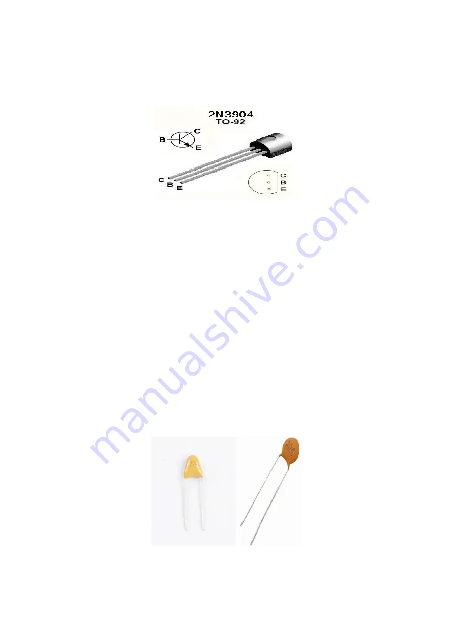
These smaller capacitors are not polarized, so they can be inserted in either direction, 0.1uF (100nF) are designated with number "104",
0.22uF (220nF) are designated with number "224
”. Insert all of these capacitors, solder in place, and snip the excess leads.


