


6
ON/OFF
1
ON/OFF
Set
LED
Neutral point
first click
second click
third click
Point of full throttle
Point of full brake
2
Set
Set
Set
#A
#B
#C
ESC
channel 2
Switch
Receiver
channel 1
Servo
Plus pole
red cable
Minus pole
black cable
Set
ON/OFF
Motor
Regolatore (installato)
Dati tecnici:
Amperaggio
60 A
Mass. prestazione
390 A
Resistenza
0,0012 Ohm
Uso
RC-Cars
Pacco batterie
max. 2 LiPo-Zellen
Tensione BEC
6,0 V
Carico BEC
3A
Tipo motori
Brushless senza sensori
Sicurezza
Surriscaldamento temperatura,
Spegnimento sottotensione batteria,
Misure
~ 48,5 x 38 x 32 mm (con ventola)
Peso
~ 90 g (senza cavi di collegamento)
Programmabile
5 Programmierschritte (Freno,
Sottocarica, Start, ecc)
Controller (installed)
Technical data:
Max. Current
60 A
Burst Current
390 A
Internal Resistance
0,0012 Ohm
For Use With
Cars or Trucks scale
Battery packs
max. 2 LiPo cells
BEC Voltage
6,0 V
BEC Current
3A
Motor Types
Sensorless Brushless motors
Protective Circuits
Temperature cut-off
Size
~ 48,5 x 38 x 32 mm (with fan)
Weight
90 g (without cable)
Programmable
5 Programming steps (Break,
Low Voltage, Start Mode etc.)
L‘uso del regolatore
Collegamento della ricevente, la batteria e il motore
Collegare il regolatore, la ricevente, la batteria, il servo e il
motore in base alla seguente tabella. Prestare attenzione alla
polarità della batteria di alimentazione. Collegare il filo rosso
al terminale ‚+‘ e il nero con il „-“ della batteria. I terminali #
‚A‘ # # B e C‘ devono essere collegati ai morsetti del motore.
Il tasto ‚SET‘ viene usato per la programmazione. Collegare
l‘uscita del „canale 2“ della ricevente con il regolatore. Osser-
vate l‘assegnazione dei canali sul telecomando. Collegare
le uscite del regolatore ai morsetti del motore. Non esiste
un´assegnazione consigliata. Dopo che tutto è collegato, è
necessario di eseguire un test. Se il motore gira nella direzione
sbagliata e consigliato di invertire i cavi oppure verificare il tasto
reverse sul radiocomando.
Nota:
È possibile utilizzare la funzione inversa del radiocomando per
cambiare la direzione di rotazione del motore. È necessario di
riprogrammare il regolatore.
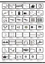
Using Your ESC
Connecting the Receiver, Battery Pack and Motor
Connect the ESC, motor, receiver, battery and servo according
to the diagram.
Ensure that you observe the correct polarity of the battery pack.
The red cable should be connected to the ‘+‘ Plus Pole and the
black cable to the ‘-‘ Minus Pole. The ’#A’, ’#B’ and ’#C’ plugs are
connected to the motor. The ‘SET‘ button initiate the program-
ming mode.
The ESC should be plugged into the throttle channel of your re-
ceiver which is normally channel 2. If in doubt, check your Radio-
Control System’s instructions. The 3 Motor wires (#A’, ’#B’ und
’#C’) can now be connected, these connectors can be plugged in
any order, and if the motor rotates in the wrong direction any 2 of
the wires should be swapped.
Note:
You can use the servo reverse function of your transmitter to
reverse the motor direction but the ESC will have to be re-ca-
librated afterwards.
Apprendimento della corsa gas / freno
Per prestazioni ottimali, il regolatore deve essere calibrato. In tal modo, le tre
posizioni avanti, indietro e la posizione di folle devono essere specificata.
Durante la regolazione procedere come segue:
1. Accendete il radiocomando, durante che la ricevente è spento. La corsa servo deve essere in
posizione neutrale. Fare attenzione che la funziona ABS sia spenta.
2. Poi accendere la ricevente tramite l‘interruttore sul regolatore. Tenendo premuto il tasto ‚SET‘.
Questo vi porterà alla modalità di calibrazione, il LED inizia a lampeggiare. Appena il LED
lampeggia, rilasciare il pulsante. Se non si rilascia il tasto ‚SET‘ subito dopo il LED inizia a
lampeggiare e si entra nella modalità di programmazione. Se non si desidera questo, è
necessario a spegnere nuovamente il regolatore. La figura seguente mostra il processo
d’inizio di calibratura.
3. E´possibile configurare tre parametri:
Posizione neutra, Fine corsa marcia avanti, Fine corsa marcia indietro
4. Portare la leva del gas in posizione neutrale e premere il tasto ‚SET‘, il LED verde lampeggia
una volta e il motore emette un suono. Portare la leva del gas in posizione finale per il
movimento in avanti e premere il tasto `SET il LED verde lampeggia due volte e il motore
emette due suoni. Portare la leva del gas in posizione finale per il movimento indietro e
premere il tasto `SET`, il LED verde lampeggia tre volte e il motore emette tre suoni. Attendere
tre secondi, dopodiché è terminato il processo di calibrazione.
Throttle range calibration
To ensure that your ESC operates correctly it has to be calibrated. During this process the full
throttle, stop and brake positions will be set.
To calibrate the system, please proceed as follows:
1. Switch ON the transmitter. The throw should be set to neutral. If the transmitter is fitted with an
ABS function this must be de-activated.
2. Press and hold down the ‘SET‘ button on the ESC and switch the receiver switch ON. The
LED will begin to blink. If you fail to release the ‘SET’ button the ESC will enter ‘Programming’
mode. If this happens, you will have to switch the ESC off and start again to enter ‘Calibration’
mode.
3. Parameters can be set here:
Neutral point, Full throttle forwards, Full throttle reverse
4. Ensure that the throttle control is in the neutral position and press the ‘Set‘ button. The green
LED will flash once and the motor will omit a beep. Move the throttle control to the full throttle
(forwards) position and press the green ‘Set‘ button. The green LED will flash twice and the
motor will omit 2 bleeps. Move the throttle control to the full reverse position and press the
‘Set‘ button. The green LED will flash 3 times and the motor will omit 3 bleeps. 3 Seconds after
this procedure has been followed, the motor is ready for use.
Gusto presa sul SET Stampato
interruttore
Lasciate che il pulsante SET quando
le luci rosse lampeggiano crostate
Hold the SET keep button
Turn on the switch
Release the SET button as soon
as the red LEDstarts to blink
LED verde
lampeggia una volta
Green LED flashes
once
LED verde
lampeggia due volte
Green LED
flashes twice
LED verde
lampeggia tre volte
Green LED
flashes thrice


