background image

11

Pegue las piezas F29 - F33 como se muestra arriba.

Use instant glue to secure F29-F33 in place with SF logo facing 

top.

Cuando el pegamento se haya secado, cubra las piezas F34 con 

pegamento y péguelas en el soporte del motor para reforzarlas 

(véase la imagen).

When the glue is dried enough; spread some epoxy on F34 and 

secure F34 inside the motor mount; spread some epoxy on the 

corners of F34 for reinforcement.

Después  de  que  el  pegamento  se  haya  secado,  pegue  el  so-

porte del motor a la parte delantera del fuselaje. Para asegurar, 

pegue un F35 a la derecha e izquierda del soporte del motor.

When the glue is dried enough; install the motor mount inside the 

head of fuselage, use instant glue to secure the motor mount in 

place. Place F35 inside the motor mount and use epoxy to secu-

re it in place. Spread some epoxy on two sides of motor mount.

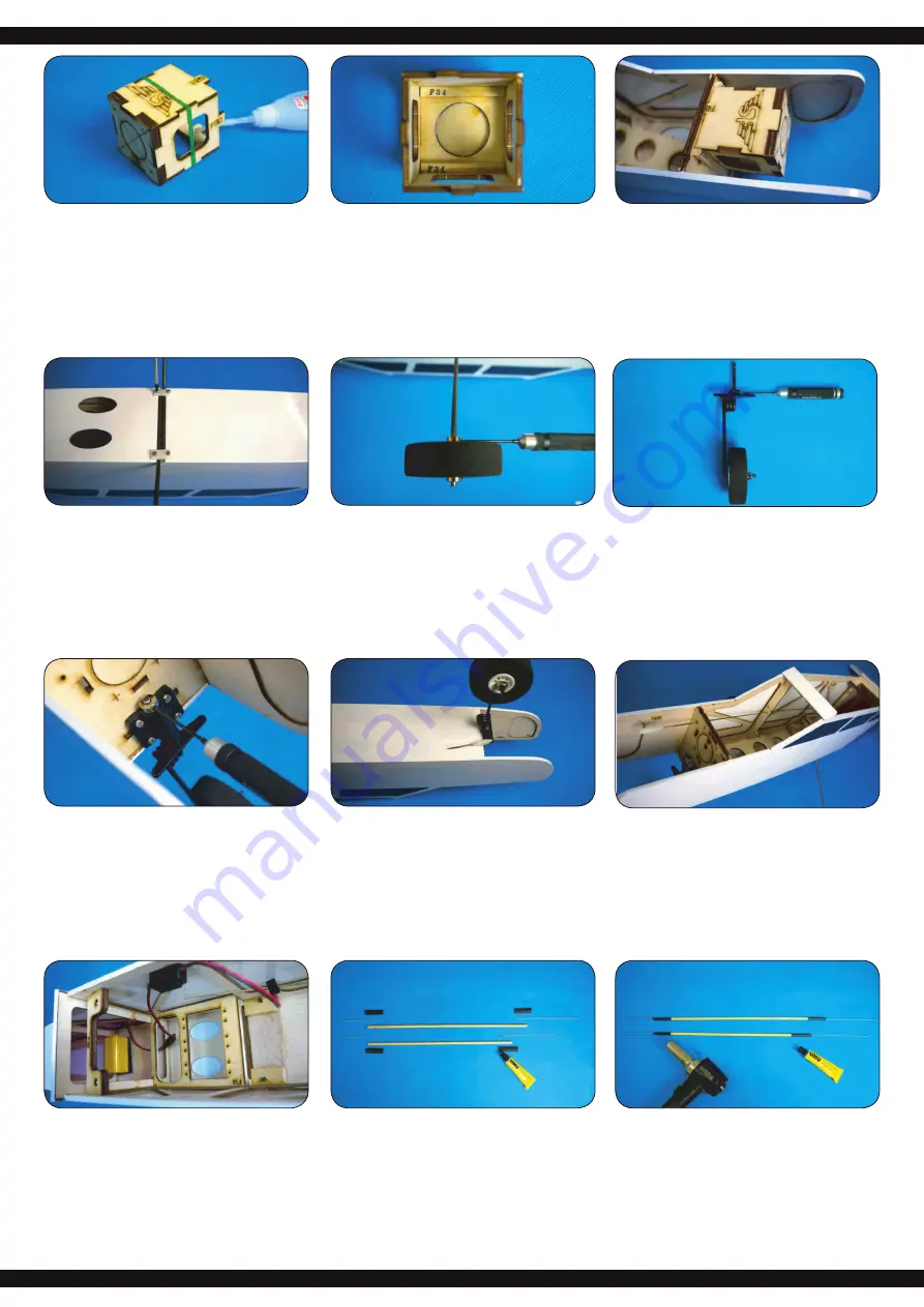
Atornille el morro del tren de aterrizaje en el soporte del tren de 

aterrizaje en la parte delantera del mamparo, asegurándose de 

que la capacidad de dirección no se vea afectada.

Install  nose  gear  assembly  into  the  nose  gear  mount,  place  a 

collar on top of it and secure with M3x4mm hex screw. Install 

nose gear assembly into the nose gear mount, place a collar on 

top of it and secure with M3x4mm hex screw.

Retire una varilla roscada M2 x 450 mm, atornille la cabeza de 

la horquilla y deslice un pequeño pieza de tubo de silicona sobre 

la varilla roscada. Enganche la horquilla a la parte delantera del 

timón del tren de atterizaje delantero.

Take  on  piece  of  M2  x  450mm  rod  out  of  the  hardware  bag; 

screw in clevis on one end; slide in a small piece of silicon tube,

pull the rod through the fuselage, and screw in clevis on another 

end for connecting with nose gear control horn.

Ejemplo de instalación cuando se utiliza un motor de com-

bustión

A   Retire una varilla roscada M2 x 450 mm del kit e


introdúzcala a través del hueco en la parte delantera del 


fuselaje. Coloque una tubo de silicona en la parte delantera 


y atornille la cabeza de la horquilla a la varilla roscada.

Installation example when using a combustion motor:

A   Take one piece of M2 x 450mm rod out of the hardware bag 


and insert through the pre-served holes inside the fuselage. 


Thread the clevis on the end of rod and slide in one piece of


 silicone tube.

El tren de aterrizaje principal se presiona en la ranura de la parte 

inferior del fuselaje y se atornilla con los soportes suministrados.

Use 2.6 x 8 mm tapping screws and gear plates to secure the 

main gear in main gear slot. 

Fije las ruedas al tren de aterrizaje respectivo utilizando dos anil-

los de ajuste cada uno. Preste atención al buen funcionamiento 

de las ruedas.

Assemble wheel with collars on the main gear and secure with 

M3 x 4 mm hex screw. Make sure the wheels can turn easily.

Montar el tren de aterrizaje delantero.

Install nose gear control horn on the top of nose gear; secure 

with M3x4mm hex screw.

Instale la batería del receptor y el cable del interruptor.

B   Install the receiver battery and switch.

Observe la imagen de arriba y monte las varillas para el timón 

de  profundidad  y  dirección.  Usar  el  pegamento  para  asegurar 

la construcción.

Please refer to the drawing and assemble the rods for the eleva-

tor and rudder. Use UHU glue to secure the conjunctions.

Deslice el tubo retráctil sobre las conexiones y encájelas con un 

secador de aire caliente.

Slide in shrinking tube on the conjunction. Use heat gun to make 

the tube shrinking for reinforcement.

Содержание Air Trainer 46

Страница 1: ...un ngulo de 90 con respecto al larguero principal y p guelos con el pegamento Refer to the assemble drawing inside the box and fit ribs W8 W9 onto the W2 combination Use triangle ruler between the rib...

Страница 2: ...nto Lijar cuidadosamente con papel de lija los restos de adhesivo y los desniveles Top planking Try to fit W13 W14 and W16 in order Make sure they are align ment and drop some instant glue to secure t...

Страница 3: ...esniveles Use planer and sanding paper to trim the leading edge Coloque el revestimiento en la parte superior del ala y aseg rese de que est correctamente alineado Place the top planking on the main w...

Страница 4: ...re them together Ahora inserte el conector de ala W29 en el hueco de la costilla de la ra z Si esto no encaja perfectamente lijar para que encaje con papel de lija Try to fit the wing joiner into the...

Страница 5: ...cto Use instant glue to secure F3 4 F6 and F8 on side planking Inserte F3 4 F6 y F8 en los respectivos huecos de F2R La mar ca de F3 debe apuntar hacia afuera No se pegue Coloque la placa de la bater...

Страница 6: ...ace Inserte el soporte del tren de aterrizaje en la parte inferior del fu selaje en el hueco previsto a tal efecto Si el soporte est correc tamente asentado puede pegarlo en su lugar con el pegamento...

Страница 7: ...dos partes encajen a ras Use sanding paper to trim the surface where V1 meets V2 Pegar V1 y V2 con el pegamento Use instant glue to secure V1 on V2 Ahora coloque la cobertura de la cabina en la parte...

Страница 8: ...Pegue las bisagras del tim n en el tim n de direcci n y plano de cola lateral Use epoxy to secure the hinges into the rudder and vertical Coloque las siguientes piezas en su superficie de trabajo Serv...

Страница 9: ...ay for reinforcement Pase el cable de conexi n del servo desde el racor atornilla do para cables a trav s de la alea hasta el servoeje Instale la cobertura del servo en el ala Connect the extension wi...

Страница 10: ...madera Ahora quite la hoja Remove the covering inside the marking on the fuselage Be careful not to cut into the wood as doing so will weaken the construction Marque los dos ranuras para el tim n de...

Страница 11: ...rod through the fuselage and screw in clevis on another end for connecting with nose gear control horn Ejemplo de instalaci n cuando se utiliza un motor de com busti n A Retire una varilla roscada M2...

Страница 12: ...p around the battery tray Connect the RSC with battery for checking the motor rotation The rotation must be anticlockwise H Monte la h lice y el cono en la parte delantera del motor H Assemble propell...

Страница 13: ...arilla y el conducto de ventilaci n en el dep sito Aseg rese de conectar correctamente los tubos Pegue una pieza de cinta de velcro en la parte inferior del dep sito de combustible y en el tablero de...

Страница 14: ...as exiones del tim n Esta informaci n sirve de gu a tambi n puede establecer otros valores 1 Flap de aterrizaje si est instalado a Despeguet 30 b Aterrizar 45 o m s 2 Aler n arriba abajo 15 mm 15 mm 3...

Страница 15: ...ervo Servo ap de aterrizaje Flap servo Servo aler n Aileron servo Servo aler n Aileron servo Servo aler n Aileron servo Servo aler n Aileron servo Servo Gas Throttle servo Motor Regulador Brushless Br...

Страница 16: ...alquier da o que resulte de la operaci n de un avion de modelo GB Security instructions The user is fully responsible for the construction and the correct use of the model If this model is the first r...

Отзывы: