background image


CM-200GE/CM-200GE-RA/CB-200GE/CB-200GE-RA  


- 44 - 

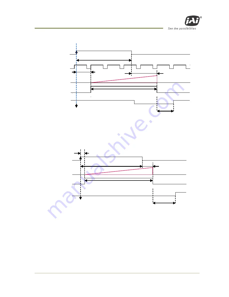
10.2.3.1   LVAL_sync timing 


Trig

CCD Exposure

Exposure

EEN

FVAL

1L to 2L

2L

1L(Max)

LVAL

LVAL SYNC Mode Setting

Trigger input whthin FVAL HIGH Period

2L (min.)


Fig. 30.   Pulse width control. LVAL sync. 


10.2.3.2   LVAL_async timing 


5.37 μs ± 1 μs

CCD exposure

Trig

2L to 3L

EEN

FVAL

Exposure

1L

Trigger input during FVAL LOW period
LVAL a-SYNC mode setting

2L (min.)


Fig.31. Pulse Width control LVAL async 


Содержание CB-200GE

Страница 1: ...CM 200GE CB 200GE CM 200GE RA CB 200GE RA Digital Monochrome Color Progressive Scan GigE Vision Camera Document Version 2 2 CMB 200GE_Ver 2 2_Aug2018 User s Manual ...

Страница 2: ...ndard part 1 FCC This equipment has been tested and found to comply with the limits for a Class B digital device pursuant to Part 15 of the FCC Rules These limits are designed to provide reasonable protection against harmful interference in a residential installation This equipment generates uses and can radiate radio frequency energy and if not installed and used in accordance with the instructio...

Страница 3: ...n Products known as China RoHS The table shows contained Hazardous Substances in this camera mark shows that the environment friendly use period of contained Hazardous Substances is 15 years 嶷勣廣吭並 嗤蕎 嗤墾麗嵎賜圷殆兆各式根楚燕 功象嶄鯖繁酎慌才忽佚連恢匍何〆窮徨佚連恢瞳麟半陣崙砿尖一隈〇 云恢瞳ゞ 嗤蕎 嗤 墾麗嵎賜圷殆兆各式根楚燕 泌和 桟隠聞喘豚 窮徨佚連恢瞳嶄根嗤議嗤蕎嗤墾麗嵎賜圷殆壓屎械聞喘議訳周和音氏窟伏翌 亶賜融延 窮徨佚連恢瞳喘薩聞喘乎窮徨佚連恢瞳音氏斤桟廠夛撹冢嶷麟半 賜斤児繁附 夏恢夛撹冢嶷鱒墾議豚 方忖仝15々葎豚 15定 ...

Страница 4: ...n Products known as China RoHS The table shows contained Hazardous Substances in this camera mark shows that the environment friendly use period of contained Hazardous Substances is 15 years 嶷勣廣吭並 嗤蕎 嗤墾麗嵎賜圷殆兆各式根楚燕 功象嶄鯖繁酎慌才忽佚連恢匍何〆窮徨佚連恢瞳麟半陣崙砿尖一隈〇 云恢瞳ゞ 嗤蕎 嗤 墾麗嵎賜圷殆兆各式根楚燕 泌和 桟隠聞喘豚 窮徨佚連恢瞳嶄根嗤議嗤蕎嗤墾麗嵎賜圷殆壓屎械聞喘議訳周和音氏窟伏翌 亶賜融延 窮徨佚連恢瞳喘薩聞喘乎窮徨佚連恢瞳音氏斤桟廠夛撹冢嶷麟半 賜斤児繁附 夏恢夛撹冢嶷鱒墾議豚 方忖仝15々葎豚 15定 ...

Страница 5: ...s and outputs table 16 6 4 Configuring the GPIO module register settings 17 6 4 1 Input Output Signal Selector 17 6 5 Examples of the pulse generator configuration 17 6 5 1 Setting screen of the pulse generator 17 6 5 2 GPIO Plus PWC shutter 18 6 5 3 Internal Trigger Generator 19 7 Image output signal 20 7 1 Output image 20 7 2 Vertical Binning CM 200GE CM 200GE RA only 20 7 3 Digital Video Output...

Страница 6: ...l Trigger Mode Pre Select trigger 46 10 2 6 Delayed Readout Mode Pre Select trigger and pulse width trigger 48 10 2 7 Optical Black transfer Mode 49 10 2 8 Operation Mode and Functions matrix 50 11 JAI control tool 51 11 1 About GenICamTM SFNC1 3 51 11 2 JAI SDK Ver 1 3 51 11 3 Examples of camera operation 52 11 3 1 Generic cautions for operation 52 11 3 2 Connection of camera s 52 11 3 3 Camera s...

Страница 7: ...ision Association The purpose of the GenICam standard is to provide a common program interface for various machine vision cameras By using GenICam cameras from different manufactures can seamlessly connect in one platform For details about the GigE Vision standard please visit the AIA web site www machinevisiononline org and for GenICam the EMVA web site www genicam org JAI GigE Vision cameras com...

Страница 8: ... RA also comply with the GenICam standard and contains an internal XML file that is used to describe the functions features of the camera For further information about GigE Vision standard please go to www machinevisiononline org and about GenICamTM please go to www emva org As an application programming interface JAI provides an SDK Software Development Kit This SDK includes a GigEVision Filter D...

Страница 9: ... 40 ms in Full Frame scan Sequencer trigger mode for on the fly change of gain exposure and ROI Edge pre select and Pulse width trigger mode LVAL synchronous asynchronous operation auto detect Auto iris lens video output allows a wider range of light GigE Vision Interface with 10 or 8 bit output Programmable GPIO with opto isolated inputs and outputs Can be connected with 100BASE TX Right Angle ty...

Страница 10: ...two screws located above and below the Ethernet connector Note 2 Mounting holes M3 depth 3 5mm for tripod mount plate Note 3 1 Note Rear protrusion on C mount lens must be less than 10 0mm 2 Note When a RJ 45 cable with thumbscrews is connected to the camera please do not excessively tighten screws by using a screw driver The RJ 45 receptacle on the camera might be damaged For security the strengt...

Страница 11: ... and below the Ethernet connector Note 2 Mounting holes M3 depth 3 5mm for tripod mount plate Note 3 1 Note Rear protrusion on C mount lens must be less than 10 0mm 2 Note When a RJ 45 cable with thumbscrews is connected to the camera please do not excessively tighten screws by using a screw driver The RJ 45 receptacle on the camera might be damaged For security the strength to tighten screws is l...

Страница 12: ...erating in Continuous mode Flashing green The camera is receiving external trigger Ethernet connector indicates Steady green 1000 Base T has been connected Flashing green 100 Base T has been connected Note Flashing amber Network active in communication Note When 10 Base T is connected the green is flashing However the video Is not streamed through Ethernet Fig 3 Rear Panel POWER TRIG GigE ...

Страница 13: ...tor for details on recommended industrial RJ 45 connectors Fig 5 Gigabit Ethernet connector The digital output signals follow the Gigabit Ethernet interface using RJ 45 conforming connector The following is pin assignment for Gigabit Ethernet connector Pin No In Out Name 1 In Out MX1 DA 2 In Out MX1 DA 3 In Out MX2 DB 4 In Out MX3 DC 5 In Out MX3 DC 6 In Out MX2 DB 7 In Out MX4 DD 8 In Out MX4 DD ...

Страница 14: ...enerator Setting 0 Start Point Counter 0 1 Length counter 0 Start Point Counter 0 2 for repeat End point counter 0 Counter 0 clear Pulse Generator Setting 1 Pulse Generator 1 Pulse Generator 1 18 19 Pulse Generator 2 Pulse Generator 3 14 15 Pulse Generator Setting 2 Pulse Generator Setting 3 Pulse Generator 2 20 bit Counter Pulse Generator 3 20 bit Counter Fig 6 GPIO bloack The input and output se...

Страница 15: ...the configured pulse width starting point and end point Fig 7 Generalted pulse The following example shows the FVAL input to pulse generator The pulse generator creates the pulse using FVAL and the pulse is output through GPIO PORT 1 The pixel clock is 60MHz Setting example Pulse Generator 0 IN FVAL 0 1 2 3 1 99 100 101 102 103 2 1 Start Point 0 End Point 99 Length 102 Clock IN Clock Source Pixel ...

Страница 16: ... SDK 6 2 Opto isolated Inputs Ouputs The control interface of the C3 GigE Vision camera series has opto isolated inputs and outputs providing galvanic separation between the camera s inputs outputs and peripheral equipment In addition to galvanic separation the opto isolated inputs and outputs can cope with a wide range of voltages the voltage range for inputs is 3 3V to 24V DC whereas outputs wil...

Страница 17: ...ne c tor hiros e 12 c onne c tor Use r sid e JAI C3_Series CAMER A sid e E XTE RN A L IN P U T 3 3V IN Fig 10 External Input Circuit OPT IN 1 and 2 6 2 2 Recommended External Output circuit diagram for customer hirose 12 connector Pin 8 and 10 hirose 12 connector Pin 7 and 9 OUT 270 5V to 24V User Power 2 User side Camera Inside From Camera Circuit EXTERNAL OUTPUT 12V 220 To Fig 11 External Output...

Страница 18: ...um Output Pulse Width 20us Time Delay Rise TDR 0 5us 0 7us Rise Time RT 1 2us 3 0us Time Delay Fall TDF 1 5us 3 0us Fall Time FT 4 0us 7 0us Fig 12 Opto isolated Interface Performance 6 3 Inputs and outputs table Output Port Trigger 0 Trigger 1 OPT OUT1 OPT OUT2 Time Stamp Reset Pulse Gen 0 Pulse Gen 1 Pulse Gen 2 Pulse Gen 3 Input Port LVAL IN DVAL IN FVAL IN EEN IN OPT IN 1 OPT IN 2 Soft Trigger...

Страница 19: ...al Selector Line selector This sets the input and output to the external equipment Line 3 through line 6 are already allocated as below Line source This sets which signal can be fed through selected output external or internal 6 5 Examples of the pulse generator configuration 6 5 1 Setting screen of the pulse generator ...

Страница 20: ...lue 0 Pass through Length Counter 0 1000 Clocks Start point Counter 0 100 Clocks Repeat Count 0 1 End point Counter 0 750 Clocks Counter Clear 0 Rising Edge Trigger source pulse generator 0 LUT Cross point switch 12bit Counte Pulse Generator 2 20bit Counter Pulse Generator 1 20bit Counter Pulse Generator 0 20bit Counter LUT 12bit Pulse Generator 3 20bit Counter LVAL IN DVAL IN FVAL IN EEN IN OPT I...

Страница 21: ...t Counter 0 500 Clocks Clear activation Off Trigger source pulse generator 0 LUT Cross point switch 12bit Counte Pulse Generator 2 20bit Counter Pulse Generator 1 20bit Counter Pulse Generator 0 20bit Counter LUT 12bit Pulse Generator 3 20bit Counter LVAL IN DVAL IN FVAL IN EEN IN OPT IN 1 OPT IN 2 Soft Trigger 0 Soft Trigger 1 Soft Trigger 2 Soft Trigger 3 Cross Point Switch Trigger 0 Trigger 1 O...

Страница 22: ...cal black pixels in the image stream 7 2 Vertical Binning CM 200GE CM 200GE RA only The binning functions can be used to achieve higher frame rate or higher sensitivity The drawback is lower resolution Vertical binning is done by adding the charge from pixels in adjacent lines in the horizontal CCD register Fig 11 shows the binning principle Resolution and frame rate for all combinations are shown...

Страница 23: ...vel equals 100 video output Fig 17 Digital Output 7 3 1 Bit Allocation Pixel Format Pixel Type CM 200GE CM 200GE RA monochrome In the GigE Vision Interface GVSP GigE Vision Streaming Protocol is used for an application layer protocol relying on the UDP transport layer protocol It allows an application to receive image data image information and other information from a device In CM 200GE CM 200GE ...

Страница 24: ...7 0 1 2 3 4 5 6 7 G0 B1 G2 7 3 2 2 GVSP_PIX_BAYRG10 Bayer RG10 Odd Line 1 Byte 2 Byte 3 Byte 4 Byte 0 1 2 3 4 5 6 7 8 9 X X X X X X 0 1 2 3 4 5 6 7 8 9 X X X X X X R0 R0 G1 G1 Even Line 0 1 2 3 4 5 6 7 8 9 X X X X X X 0 1 2 3 4 5 6 7 8 9 X X X X X X G0 G0 B1 B1 7 3 2 3 GVSP_PIX_BAYGB8 BayerGB8 Odd Line 0 1 2 3 4 5 6 7 0 1 2 3 4 5 6 7 0 1 2 3 4 5 6 7 G0 B1 G2 Even Line 7 3 2 4 GVSP_PIX_BAYGB10 Baye...

Страница 25: ...he center might be shifted As Pixel Format type the CB 200GE CB 200GE RA support BAYER GB 8 and BAYER GB 10 When this type is selected the output starts from 2nd line for all scanning 7 4 CB 200GE CB 200GE RA Bayer mosaic filter CB 200GE CB 200GE RA is a color camera based on a CCD sensor with a Bayer RGB color mosaic The color image reconstruction is done in the host PC The Color sequence in the ...

Страница 26: ... 38 ns LVAL DATA OUT DVAL Valid data 1628 clk 1688 clk 1624 clk OB 4 clk 48 clk 392 clk OB 12 clk OB 16 clk 32 clk 1640 clk Fig 19 Horizontal timing 7 5 2 Vertical timing The FVAL period for normal continuous mode full scan is shown Vertical Video Timing Full Frame Read out Frame rate 1251L 24 98fps LVAL FVAL DVAL DATA EEN 1 2 3 1234 1235 1236 1236L 2L OB OB Valid data 3L 10L CCD Exposure OB Fig 2...

Страница 27: ...e fixed partial scan settings 1 2 1 4 1 3 and 2 3 LVAL FVAL DVAL DATA 3L CCD Exposure EEN A B C Partial Frame Readout Valid data Values for vertical timing in partial scan continuous mode Fig 21 Vertical timing for partial scanning AREA FVAL Low L A L B L C L Total line frame rate fps Start line End line 1 2 3 48 616 46L 713L 43 82 311 926 1 4 3 70 308 68L 449L 69 59 465 772 1 8 3 81 156 79L 319L ...

Страница 28: ...nning combines charge from two adjacent lines reducing the vertical resolution to half and at the same time increasing frame rate and sensitivity By activating this function the frame rate is increased to 44 492 fps This function is available only for CM 200GE CM 200GE RA Important Note Vertical Binning can not be used together with the Partial Scanning 7 5 4 1 Horizontal Timing Horizontal Video T...

Страница 29: ...al is not routed through the GPIO This signal is available at pin 4 of 12 pin Hirose connector It can be used for lens iris control in Continuous and RCT modes only The signal is taken from the CCD sensor output after the gain circuit The video output is without sync The signal is 0 7 V p p from 400 Ω AC coupled Fig 25 Iris Video Circuit To use this signal the internal DIP switch must be set as fo...

Страница 30: ...ing multiple cameras going through a switch and or a single path or when operating in a system with limited transmission bandwidth the Delayed Readout Mode and Inter Packet Delay functions can be useful 8 2 Equipment to configure the network system 8 2 1 PC The PC used should have the following performance or better 1 Recommended CPU Core2 Duo 2 4GHz or better Better than Core2 Extreme 2 Recommend...

Страница 31: ...40GE and CB 140GE series conform to Gigabit Ethernet IEEE 802 3 not all combinations of network interface cards NICs and switches routers are suitable for use with the GigE Vision compliant camera JAI will endeavor to continuously verify these combinations in order to give users the widest choice of GigE components for their system design For details of the network settings please refer to the Get...

Страница 32: ...rate a larger packet size produces a slightly lower data transfer rate The CM 200GE and CB 200GE sereis can support a maximum of 4040 byte packets provided the NIC being used has a Jumbo Frames function with a setting of a 4040 bytes or larger Caution Do not set the packet size larger than the maximum setting available in the NIC or switch to which the camera is connected Doing so will cause outpu...

Страница 33: ... 2 x8x25 1000000 416 Mbit s 8 3 5 Simplified calculation Approximate value A simple way to calculate the approximate data transfer rate is the following Transfer data Image width pixel x Image Height pixel x depth per pixel depending on the pixel format x frame rate 1 000 000 convert to mega bit In the case of the CM 200GE with the full image and MONO8 pixel format The data transfer rate 1624 x 12...

Страница 34: ...tely in order for the data not to overflow in the switching hub 8 4 2 Connecting a camera to each port of a multi port NIC This is the example for using a 4 port NIC The pair of the connecting camera and the NIC constructs one subnet As for the IP configuration it is appropriate to use the persistent IP In this case each camera can use the maximum 800Mbps bandwidth However the load for the interna...

Страница 35: ...The packet delay should be set larger The data traffic is controlled by the buffer of the hub It is necessary to check the buffer value of the unit 8 4 3 2 If delayed readout is not used in trigger mode The packet delay should be set larger The data traffic is controlled by the buffer of the hub It is necessary to check the buffer value of the unit ...

Страница 36: ... CB 200GE CB 200GE RA 34 8 4 3 3 If delayed readout is used The packet delay should be set smaller and the packet delay trigger controls the data traffic If the camera has a pulse generator it can control the data traffic ...

Страница 37: ...n the functions are described in detail 9 2 Electronic Shutter In the GenICam SFNC interface the electronic shutter is set by Exposure time microseconds The traditional JAI method for shutter setting can also be used including JAI Shutter Mode JAI Preset Shutter JAI Exposure Time Raw and JAI Exposure Time us If setting is done using the SFNC method these settings are automatically reflected in the...

Страница 38: ...Scan 64 us 10 208 μs V Binning Scan 71 692 us 22 476 μs GPIO in combination with Pulse Width trigger More precise exposure time can be obtained by using GPIO in combination with Pulse Width trigger mode The clock generator and counter can be programmed in very fine increments For examples of settings refer to chapter 6 5 1 9 3 Auto detect LVAL sync async accumulation This function replaces the man...

Страница 39: ...itionStart command the image can be output until AcqusitionStop Trigger is input Single Frame By executing AcquisitionStart command one frame of the image can be output and then the acquisition is stopped Trigger Selector This can be selected from FrameStart or TransferStart FrameStart The trigger pulse can take one frame capture TransferStart The trigger pulse can read out the image stored in the...

Страница 40: ...TriggerWidth The exposure is the same as the trigger width The CM 200GE and CB 200GE series have a JAI Acquisition and Trigger Control function which is the same as used for previous models and includes 7 types of exposure modes Acquisition and Trigger Control and JAI Acquisition and Trigger Control are linked to each other and if the one is set the setting parameters are reflected in the other Th...

Страница 41: ...s or microseconds and the setting values are reflected in the same items of Acquisition and Trigger Control Other parameters such as trigger signal should be set in Acquisition and Trigger Control The following description uses JAI Acquisition and Trigger Control and the operation mode can be selected in JAI Exposure Mode ...

Страница 42: ...xposure 4 Reset continuous trigger mode Pre selected exposure 5 Sequential Trigger Pre selected exposure 6 Delayed Readout Trigger Pre selected exposure 10 2 1 Continuous operation For applications not requiring asynchronous external trigger but where a continuous stream of images is required this mode should be used In this mode it is possible to use a lens with video controlled iris For timing d...

Страница 43: ...ig 24 and fig 28 and 29 To use this mode Important notes on using this mode Trigger pulse 2 LVAL to 1 FVAL The following table shows minimum trigger interval in synchronous accumulation mode Full scan 1254 L 2 3 partial 894 L 1 2 Partial 716 L 1 4 Partial 452 L 1 8 Partial 322 L 1 2 V Binning 630 L 1 In case of a synchronous mode the exposure time should be added to the above table 2 In order to k...

Страница 44: ...VAL SYNC Mode Setting 2L Exposure 1L max Trigger input whthin FVAL HIGH Period Fig 28 Edge Pre select LVAL sync Timing 10 2 2 2 LVAL_async timing 5 37 μs 1μs CCD exposure EEN FVAL 2L to 3L Exposure time Trig Trigger input during FVAL LOW period LVAL a SYNC mode setting 2L min Fig 29 Pre select LVAL async Timing ...

Страница 45: ...ulting video signal will start to be read out after the trigger rising edge For timing details refer to fig 19 through fig 24 and fig 30 and 31 To use this mode Important notes on using this mode Trigger pulse width 2 LVAL to 2 seconds The following table shows minimum trigger interval in synchronous accumulation mode Full scan 1254 L 2 3 Partial 894 L 1 2 Partial 716 L 1 4 Partial 452 L 1 8 Parti...

Страница 46: ...L 2L 1L Max LVAL LVAL SYNC Mode Setting Trigger input whthin FVAL HIGH Period 2L min Fig 30 Pulse width control LVAL sync 10 2 3 2 LVAL_async timing 5 37 μs 1 μs CCD exposure Trig 2L to 3L EEN FVAL Exposure 1L Trigger input during FVAL LOW period LVAL a SYNC mode setting 2L min Fig 31 Pulse Width control LVAL async ...

Страница 47: ... by the pre set shutter speed If no further trigger pulses are applied the camera will continue in normal mode and the video signal is not output The fast dump read out has the same effect as smearless read out Smear over highlight areas is reduced for the trigger frame The reset continuous trigger mode makes it possible to use triggering in conjunction with a lens with video controlled iris To us...

Страница 48: ... from the preset sequence is output as described below Trigger Sequence Operation Signals added to trigger can be selected by Trigger Spurce The camera will functions on the rising edge of the trigger and Negative or Positive should be determined accordingly For the sequence the following default settings are installed ID ROI Shutter Gain Width Height Offset X Offset Y 1 1624 1236 0 0 1251 0 2 162...

Страница 49: ...s mode Full Scan 2 3 Partial 1 2 Partial 1 4 Partial 1 8 Partial 1 2 V Binning 1255 L 895 L 717 L 453 L 323 L 631 L The condition for this table is that shutter speed should be set the same for all sequences If the shutter speed is different the difference of exposure time should be added It is recommended to set the exposure time in the order from the shortest to the longer one For proper operati...

Страница 50: ...ed to the same GigE interface it allows the cameras to be read out in sequence preventing congestion The image data is not transmitted directly by the trigger 0 and it is stored in the memory located at Ethernet Interface By the falling edge of the soft trigger 1 the image data is output Trigger 0 CCD Photodiode CCD transfer gate GigE Memory Trigger 1 Ethernet Output Exposure CCD Output Store in t...

Страница 51: ...n software The default condition is OFF OB Transfer Mode OFF OB Transfer Mode ON Normal Scan 1 1624 1 1236 1 1624 1640 1 10 1 6 pixels for Horizontal 12 lines for Vertical 1246 are added 1248 2 3 Partial Scan 1 1624 1 824 1 1624 1640 1 ます 16 pixels for Horizontal are added 824 1 2 Partial Scan 1 1624 1 616 1 1624 1640 1 616 1 4 Partial Scan 1 1624 1 308 1 1624 1640 1 ます 308 1 8 Partial Scan 1 1624...

Страница 52: ... Auto No 0x02 Pulse Width PWC Not applicable Yes Yes Auto No 0x03 Reset Continuous RCT Yes Yes Yes Async only Yes Note 2 0x09 Sequential Pre select EPS Yes Yes Yes Async only No 0x17 EPS Delayed Readout Yes Yes Yes Auto No 0x18 PWC Delayed Readout Not applicable Yes Yes Auto No Note 1 Vertical Binning is available for only CM 200GE CM 200GE RA Note 2 The Auto iris output is only effective on Norma...

Страница 53: ...n of JAI GigE Vision cameras comply with GenICam SFNC1 3 However JAI can offer the following options for customers who use older versions of GIgE Vision cameras JAI provides the following software 1 Version prior to SFNC 1 3 for older camera version 2 Downgrade to old version from the latest SFNC 1 3 version Please contact local sales representatives for the details 11 2 JAI SDK Ver 1 3 JAI SDK ha...

Страница 54: ...tablishing the connection start the control tool The model name connected to the Network is displayed with connecting icon CB 200GE When this icon is double clicked the camera can communicate with the camera control tool and the icon is changed 11 3 3 Camera setting level The setting level has three layers beginner expert and guru Guru level includes the most sophisticated functions 11 4 Input and...

Страница 55: ...to Digital I O Line 1 to Line 8 The following is the example to set Line5 Opt In 1 In this case the line source is the signal connected to Opt In 1 The line format is automatically set to Opto Coupled The following is the example to set the output signal It selects the output signal from Line3 Optical Out 1 from Line source In the following example Exposure Active signal is output As the line form...

Страница 56: ... generator 0 is selected as the trigger signal 11 4 3 Setting the image size 11 4 4 Acquisition of the image The settings for image capturing are controlled in Acquisition and Trigger Control or JAI Acquisition and Trigger Control The following shows the screen After the setting of capture is completed push StartAcquisiton button As for the details of each operation mode refer to 10 Operation Mode...

Страница 57: ...file All features and registers of the camera are stored in the camera as an XML file This XML file is stored in the following folder My computer Local disk C Program files GenICam_V2 0 xml TransportLayers JAI 11 4 6 Feature Tree Information 11 4 7 Feature Properties Guru ...

Страница 58: ...CM 200GE CM 200GE RA CB 200GE CB 200GE RA 56 ...

Страница 59: ...CM 200GE CM 200GE RA CB 200GE CB 200GE RA 57 ...

Страница 60: ...CM 200GE CM 200GE RA CB 200GE CB 200GE RA 58 ...

Страница 61: ...CM 200GE CM 200GE RA CB 200GE CB 200GE RA 59 ...

Страница 62: ...ons 12 1 CM 200GE and CB 200GE GigE POWER TRIG Outsidesizetolerance F 0 3mm 44 29 C Mount 13 26 26 1 73 1 14 14 5 0 57 0 51 5 0 2 1 02 1 02 depth0 14 59 75 Serial No 6 M3depth3 5 depth0 14 FCC seal Caution seal 67 3 M3 depth3 5 5 0 2 2 64 2 95 2 32 Fig 33 CM 200GE CB 200GE Outline ...

Страница 63: ...ount 6 M3depth 3 5 3 M3depth 3 5 depth0 14 depth0 14 depth0 14 102 5 4 04 6 3 0 25 1 14 29 31 1 22 32 5 59 8 0 31 2 32 1 28 1 02 26 Ser i al No Caut i on seal 4 M3depth 3 5 1 02 1 28 2 64 0 57 1 73 0 20 5 0 31 1 02 67 32 5 8 14 5 44 26 26 Gig E PO W E R T RIG FCC seal in inch Fig 34 CM 200GE RA CB 200GE RA outline ...

Страница 64: ...CM 200GE CM 200GE RA CB 200GE CB 200GE RA 62 13 Specifications 13 1 Spectral response Fig 35 Spectral response for CM 200GE CM 200GE RA RA Fig 36 Spectral response for CB 200GE CB 200GE RA RA IR Filter ...

Страница 65: ... enabled by internal switch Gain Manual 3 to 24 dB 1 step 0 0358dB Synchronization Internal X tal GPIO Module Input output switch Clock Generator One Pulse Generators Four Configurable 14 in 9 out switch 12 bit counter based on 25MHz clock or Pixel clock 20 bit counter programmable for length start point stop point repeat Hardware Trigger modes Edge Pre Select Pulse Width Control RCT Frame Delay a...

Страница 66: ...t lens must be less than 10 0mm Flange back 17 526mm Tolerance 0 to 0 05mm Optical Low Pass Filter Built in Only for CB 200GE CB 200GE RA Dimensions CM CB 200GE 44 x 29 x 75 mm W x H x D excluding protrusions CM CB 200GE RA 44 x 29 x 102 5 mm W x H x D excluding protrusions Weight CM CB 200GE 125 g CM CB 200GE RA 155 g For stable operation within the above specifications allow approximately 30 min...

Страница 67: ...shipped without visible image sensor blemishes Over time some pixel defects can occur This does not have a practical effect on the operation of the camera These will show up as white spots blemishes Exposure to cosmic rays can cause blemishes to appear on the image sensor Please take care to avoid exposure to cosmic rays during transportation and storage It is recommended using sea shipment instea...

Страница 68: ...e tripod mounting plate please use the provided screws 14 5 Exportation When exporting this product please follow the export regulation of your own country 14 6 References 1 This manual for CM 200GE CM 200GE RA CB 200GE CB 200GE RA can be downloaded from www jai com 2 Datasheet for CM 200GE CM 200GE RA CB 200GE CB 200GE RA can be downloaded from www jai com 3 Camera control software can be downloa...

Страница 69: ...n Sept 2009 1 2 Change the depth in chassis for screws from 4mm to 3 5mm and add caution Gain up from 12dB to 24dB Camera revision G and after Sensitivity is changed Add RCT trigger mode August 2011 2 0 Totally revised to conform with GenICam SFNC ver 1 3 February 2013 2 1 Change the power supply from 12V to 12V to 24V Aug 2018 2 2 Add KC ...

Страница 70: ... names mentioned in this manual are trademarks or registered trademarks of their respective owners JAI A S cannot be held responsible for any technical or typographical errors and reserves the right to make changes to products and documentation without prior notification Europe Middle East Africa Asia Pacific Americas Phone 45 4457 8888 Fax 45 4491 3252 Phone 81 45 440 0154 Fax 81 45 440 0166 Phon...

Отзывы: